Check patentability & draft patents in minutes with Patsnap Eureka AI!

Rotary limiting device and using method thereof

A technology of rotation limit and rotation axis, which is applied in the direction of mechanical equipment, brake types, etc., can solve the problems of poor environmental protection and large energy consumption, and achieve the effect of not easy to loosen, reduce energy consumption, and simple structure of the control system

Pending Publication Date: 2021-12-03
WUHAN MARINE MACHINERY PLANT
View PDF6 Cites 0 Cited by
  • Summary
  • Abstract
  • Description
  • Claims
  • Application Information

AI Technical Summary

Problems solved by technology

[0008] The purpose of the present invention is to overcome the disadvantages of high energy consumption and poor environmental protection existing in the prior art, and to provide a rotation limiting device that does not require continuous power supply and has a simple structure and low cost

Method used


Image

  • Rotary limiting device and using method thereof
  • Rotary limiting device and using method thereof
  • Rotary limiting device and using method thereof

Examples


Embodiment 1

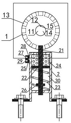
[0048] A kind of rotation limit device, the rotation limit device comprises: a rotation limit turntable 1 and a piston cylinder 2; The rotating shaft 14 is fixedly connected, the rotating limit turntable 1 is coaxially arranged with the rotating shaft 14, and a plurality of limit holes 13 are evenly opened on the outer circumference of the rotating limit turntable 1; the piston cylinder 2 is provided with A retractable piston rod 21, the piston rod 21 is arranged directly below the rotation limit turntable, the piston rod 21 passes through the top plate of the piston cylinder 2 and is inserted into the limit hole 13, and the piston rod 21 passes through it The sealing plate 22 provided on the upper part slides and cooperates with the side wall of the piston cylinder 2, and the sealing plate 22 is in sealing cooperation with the side wall of the piston cylinder 2, and the sealing plate 22 separates the piston cylinder 2 into an oil chamber 24 and a spring chamber 30, The oil ch...

Embodiment 2

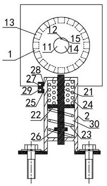
[0055] Embodiment 2 is basically the same as Embodiment 1, and its difference is:

[0056] The oil chamber 24 is arranged above the sealing plate 22, the spring chamber 30 is arranged below the sealing plate 22, the top of the spring 23 is press fit with the bottom of the sealing plate 22, and the bottom of the spring 23 is in contact with the sealing plate 22. The top of the plate 22 is a press fit.

Embodiment 3

[0058] Embodiment 3 is basically the same as Embodiment 2, and its difference is:

[0059] The number of the positioning wedge 12 is three.


PUM


Abstract

The invention discloses a rotary limiting device and a using method thereof. The rotary limiting device comprises a rotary limiting rotating disc and a piston cylinder. The rotary limiting rotating disc is of a disc structure and is coaxially and fixedly connected with a rotary shaft, and a plurality of limiting holes are evenly formed in the outer circumference of the rotary limiting rotating disc; and the piston cylinder is matched with limiting holes in an inserted mode through a telescopic piston rod arranged in the piston cylinder, a sealing plate divides the piston cylinder into an oil cavity and a spring cavity, the oil cavity communicates with a pressure oil source through a three-position three-way valve arranged on the side part of the oil cavity, a spring is arranged in the spring cavity, the top end of the spring is matched with the sealing plate in a pressing mode, and the bottom end of the spring is matched with the piston cylinder in a pressing mode. According to the rotary limiting device, the piston rod can be driven through the elastic force of the spring to limit the limiting holes, the system does not need to do work continuously, and the economical efficiency and the environmental protection property are effectively improved; and the limiting device can be controlled to work through the valve position of the three-position three-way valve, and the control system is simple and reliable in structure.

Description

technical field [0001] The invention relates to a rotation limiting device, in particular to a rotation limiting device and a usage method thereof, and is particularly applicable to a hydraulically driven rotation limiting device. Background technique [0002] The rotating machinery in the position servo control mechanism needs to stop precisely at a fixed position without being affected by the load and external factors after reaching the target position. The existing rotating machinery usually cannot maintain a certain position after losing power, and is prone to rotation due to the influence of load and external factors cause a change in position. At present, the limit of the rotating machinery in the position servo control mechanism is usually carried out in three ways: continuous power supply of the rotating machinery, mechanical brake or electromagnetic brake; [0003] The mechanical brake currently used includes a brake arm, a brake body, a brake wheel and a push rod,...

Claims


Application Information

Patent Timeline
Patent Type & Authority Applications(China)
IPC IPC(8): F16D63/00
CPCF16D63/006
Inventor 梁伟黄浩董新营
Owner WUHAN MARINE MACHINERY PLANT
Features
  • R&D
  • Intellectual Property
  • Life Sciences
  • Materials
  • Tech Scout
  • Unparalleled Data Quality
  • Higher Quality Content
  • 60% Fewer Hallucinations
Learn More