[0029] The present invention is described in further detail below:
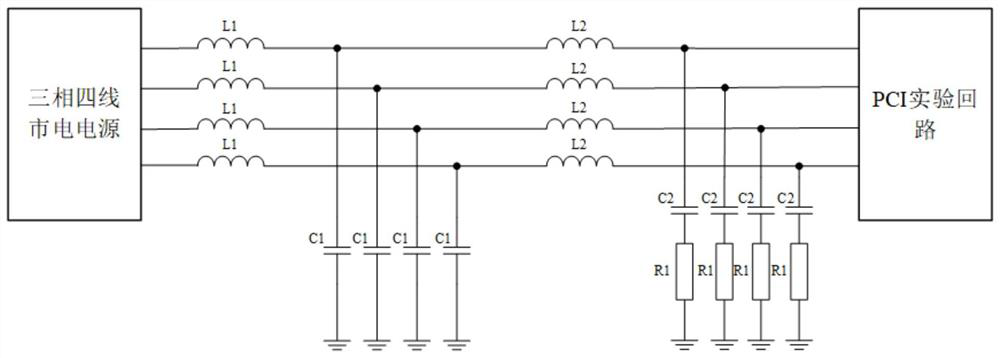
[0030] A line impedance stabilization network (LISN) structure suitable for pulse current injection, the LISN structure is designed as a three-phase four-wire structure, composed of four branches with the same circuit structure.
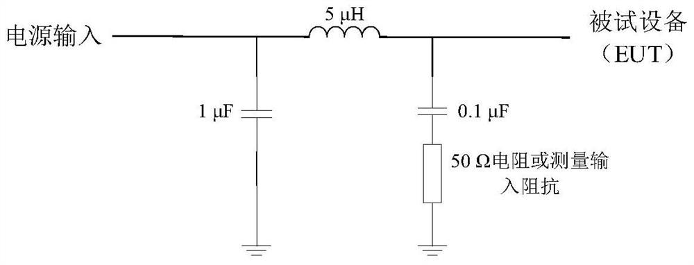
[0031] In terms of circuit structure design, on the basis of the conventional 5μH type LISN circuit structure in GJB 151B-2013, the capacitance value of the ground capacitance and the first-level inductance are increased, so the circuit structure of each branch of the LISN is an L-C-L T A type low-pass filter is connected in parallel with a capacitor-resistance branch. This structure has the impedance stability curve of the 5μH type LISN in GJB 151B-2013 and good pulse current protection performance.
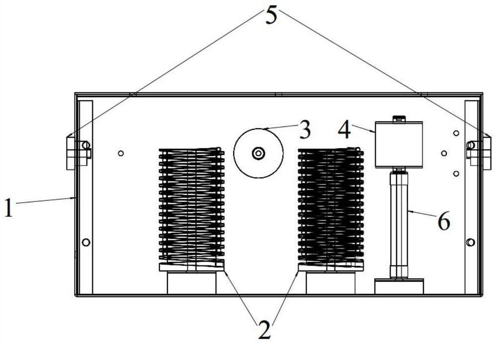
[0032]The physical structure of the LISN structure includes a stainless steel shell 1, a 5μH air core inductor with enhanced inter-turn pressure resistance 2, a 30μF polypropylene film capacitor 3, a 220nF polypropylene film capacitor 4, a high-voltage through-wall connector 5 and a 50Ω high-voltage metal oxide film resistor 6. The incoming and outgoing wires pass through the stainless steel casing 1 through the high-voltage wall-through joint 5, and the other components are fixed inside the stainless steel casing 1 by screws; in the physical structure of the circuit structure, the T-shaped low-pass filter is composed of two inter-turn resistant A pressure-enhanced 5μH air-core inductor 2 is composed of a 30μF polypropylene film capacitor 3 connected in parallel in the middle, wherein one end of the 30μF polypropylene film capacitor 3 is connected to the middle node of the two inter-turn pressure-resistant 5μH air-core inductor 2 wiring, and the other end It is fixed on the inner wall of the stainless steel shell 1 and grounded through the stainless steel shell 1; in the physical structure of the circuit structure, the capacitor inductance branch connected in parallel behind the T-shaped low-pass filter is composed of the lower end of the 220nF polypropylene film capacitor 4 and the 50Ω high-voltage metal oxide film resistor 6 The upper end is connected by M6 screw. The upper end of the 220nF polypropylene film capacitor 4 is connected to the output end of the T-type low-pass filter, and the lower end of the 50Ω high-voltage metal oxide film resistor 6 is fixed to the base of the stainless steel shell 1 by screws, and grounded through the stainless steel shell 1 through the fixing to the base; The inter-turn withstand voltage enhanced 5μH air core inductor 2 is composed of nylon skeleton and wires. The coil is wound on the nylon skeleton, and the inter-turn insulation is reinforced by a 5mm thick nylon layer to prevent the pulse current from rising too fast. As a result, the inter-turn voltage difference is too large to cause inter-turn breakdown; in order to ensure that the insulation level of the LISN meets the requirements of electromagnetic pulses, the design of the coaxial measurement port is removed, and the impedance stability is realized by a 50Ω high-voltage metal oxide film resistor 6. When in use, the mains input end is one end of a T-shaped low-pass filter structure without a parallel capacitor-resistance branch, and the output end is one end of a T-shaped low-pass filter structure parallel capacitor-resistance branch.
[0033] The technical solutions of the present invention will be clearly and completely described below in conjunction with the accompanying drawings and embodiments. Apparently, the described embodiments are only part of the embodiments of the present invention, not all of them. Based on the embodiments of the present invention, all other embodiments obtained by persons of ordinary skill in the art without making creative efforts belong to the protection scope of the present invention.
[0034] figure 2 It is the circuit structure diagram of the present invention, and it is also an explanatory diagram of the wiring mode of the present invention in actual use. This device is suitable for 380V three-phase four-wire mains power supply. One end of the branch, the mains output end is the end close to the capacitor resistance branch. Since the structure of the four branch circuits of the present invention is the same, one phase is used for illustration. In terms of circuit structure, compared with the 5μH type LISN in GJB 151B-2013, through simulation calculations for the protection performance of electromagnetic pulses, it is finally decided to add a 5μH inductor L1, and at the same time increase the capacitance of capacitor C1 and capacitor C2 Respectively increased to 30μF and 0.22μF, thereby greatly improving the electromagnetic pulse protection performance of LISN. Inductor L2, capacitor C2 and resistor R1 mainly play the role of impedance stabilization. Looking from the PCI experimental circuit to the mains, assuming that the internal resistance of the mains is R2 at this time, the mains and LISN are regarded as a whole. Resistance Z is:
[0035]
[0036] Among them, Z is the internal resistance of the mains-LISN as a whole, R1=50Ω, R2 is not a fixed value (mains internal resistance), C1=30μF, C2=0.22μF, L1=L2=5μH, ω is the angular frequency, and j is Imaginary part of impedance. In the LISN working frequency band (≥10kHz), Therefore, it can be ignored in the formula In the same way, The value of jωL is small, 2 larger, so The smaller terms can also be ignored, and finally, the above formula can be rewritten as:
[0037] Z=R 1 //L 2
[0038] That is, the internal resistance Z is equivalent to the impedance of 5μH//50Ω, which is the same as the impedance curve of the 5μH type LISN in GJB 151B-2013, and similar to the impedance curve of the 50Ω//5μH+1Ω type LISN in CISPR-16-2. Therefore, from the perspective of circuit structure, the impedance curve of the present invention meets the requirements of GJB 151B-2013 and CISPR-16-2.
[0039] image 3 It is the overall physical structure diagram of the present invention, and realized by this physical structure figure 2 The circuit structure in, including stainless steel shell 1, inter-turn pressure-resistant 5μH air-core inductor 2, 30μF polypropylene film capacitor 3, 220nF polypropylene film capacitor 4, high-voltage through-wall connector 5 and 50Ω high-voltage metal oxide film resistor 6. The incoming and outgoing wires pass through the stainless steel casing 1 through the high-voltage wall-through joint 5, and the other components are fixed inside the stainless steel casing 1 by screws; in the physical structure of the circuit structure, the T-shaped low-pass filter is composed of two inter-turn resistant A pressure-enhanced 5μH air-core inductor 2 is composed of a 30μF polypropylene film capacitor 3 connected in parallel in the middle, wherein one end of the 30μF polypropylene film capacitor 3 is connected to the middle node of the two inter-turn pressure-resistant 5μH air-core inductor 2 wiring, and the other end It is fixed on the inner wall of the stainless steel shell 1 and grounded through the stainless steel shell 1; in the physical structure of the circuit structure, the capacitor inductance branch connected in parallel behind the T-shaped low-pass filter is composed of the lower end of the 220nF polypropylene film capacitor 4 and the 50Ω high-voltage metal oxide film resistor 6 The upper end is connected by M6 screw. The upper end of the 220nF polypropylene film capacitor 4 is connected to the output end of the T-type low-pass filter, and the lower end of the 50Ω high-voltage metal oxide film resistor 6 is fixed to the base of the stainless steel shell 1 by screws, and grounded through the stainless steel shell 1 through the fixing to the base; The inter-turn withstand voltage enhanced 5μH air core inductor 2 is composed of nylon skeleton and wires. The coil is wound on the nylon skeleton, and the inter-turn insulation is reinforced by a 5mm thick nylon layer to prevent the pulse current from rising too fast. As a result, the inter-turn voltage difference is too large to cause inter-turn breakdown; in order to ensure that the insulation level of the LISN meets the requirements of electromagnetic pulses, the design of the coaxial measurement port is removed, and the impedance stability is realized by a 50Ω high-voltage metal oxide film resistor 6.
[0040] Figure 4 It is the structural diagram of the inter-turn withstand voltage enhanced air-core inductor used in the present invention. The air-core inductor has the characteristics of good high-frequency stability and no obvious saturation effect, and is more suitable for electromagnetic circuits with many high-frequency components and high current amplitudes. Pulse protection, in order to prevent electromagnetic pulse from causing insulation breakdown between turns of inductance, a 5mm thick nylon layer is designed between turns for insulation reinforcement.
[0041] Figure 5 It is the test result diagram of the electromagnetic pulse protection ability of the present invention, based on the test method of the electromagnetic pulse protection device of GJB 8848-2016 and MIL-STD-188-125-2, the electromagnetic pulse generator meets the requirements, that is, the short circuit under the 60Ω resistance load The current output peak value is 2.5kA, the rise time is ≤20ns, and the FWHM is between 500ns and 550ns. It can be seen that at this time, the front-end injection current is a nanosecond pulse with a peak value of 1.8kA, and the residual current at the rear end is attenuated into a microsecond pulse with a peak value of 30A. The attenuation factor is as high as 60 times, and it has good electromagnetic pulse protection performance.
[0042] Image 6 For the comparison chart of impedance stability curve test result of the present invention, utilize vector network analyzer (VectorNetwork Analyzer, VNA) to carry out the measurement of impedance-frequency curve, can see, compare with standard value, in electromagnetic pulse main frequency band (less than 30MHz) , and its error is less than 5%, which can meet the usage requirements in PCI experiments.
[0043] Finally, it should be noted that: the above-described embodiments are only specific implementations of the present invention, used to illustrate the technical solutions of the present invention, rather than limiting them, and the scope of protection of the present invention is not limited thereto, although referring to the foregoing The embodiment has described the present invention in detail, and those skilled in the art should understand that any person familiar with the technical field can still modify the technical solutions described in the foregoing embodiments within the technical scope disclosed in the present invention Changes can be easily thought of, or equivalent replacements are made to some of the technical features; and these modifications, changes or replacements do not make the essence of the corresponding technical solutions deviate from the spirit and scope of the technical solutions of the embodiments of the present invention, and should be included in the scope of the present invention within the scope of protection. Therefore, the protection scope of the present invention should be based on the protection scope of the claims.