A positive temperature current generating circuit
A technology for generating circuits and currents, applied in the direction of adjusting electrical variables, instruments, control/regulation systems, etc., to achieve the effects of saving circuit area, improving power supply rejection ratio, and saving system power consumption
- Summary
- Abstract
- Description
- Claims
- Application Information
AI Technical Summary
Problems solved by technology
Method used
Image

Examples
Embodiment Construction
[0011] Below in conjunction with accompanying drawing, the technical scheme of the present invention is described in detail:
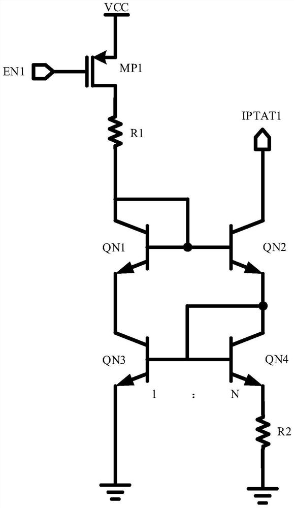
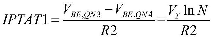
[0012] The schematic diagram of the traditional PTAT current source generation circuit is as follows figure 1 As shown, the principle of PTAT current generation is:
[0013]
[0014] The problems existing in this circuit are discussed below. The first is the problem of the degeneracy point. Because the circuit has a degeneracy point, when the enable control signal EN1 is valid, the circuit has no current path from the power rail VCC to the ground, and the circuit cannot start automatically. Additional startup circuitry needs to be added. Increased circuit complexity and system power consumption. Secondly, the transistor QN3 and the transistor QN4 are on both sides of the branch respectively, the currents through the two transistors are not completely equal, and the power supply noise and interference signals can be reflected to the current IPTAT1 ...
PUM
 Abstract
Description
Claims
Application Information