Lithium battery end structure and manufacturing method

An end structure, lithium battery technology, applied in the direction of electrolyte battery manufacturing, lithium battery, battery pack components, etc., can solve the problems of occupying lithium battery, electrolyte leakage, complexity, etc., to improve the structural connection strength and ensure compactness , use the effect of safety

Pending Publication Date: 2021-12-03
宁波久鼎新能源科技有限公司
View PDF0 Cites 0 Cited by
  • Summary
  • Abstract
  • Description
  • Claims
  • Application Information

AI Technical Summary

Problems solved by technology

[0002] At present, the end sealing is required in the production and manufacturing process of lithium batteries. The traditional way is to seal and install the current collecting plate at the end of the shell, so as to seal the battery cell and electrolyte in the shell, and then seal it in the current collecting plate. Various components such as collector rings, decorative rings, sealing rings and glands are set on the chip for conductive sealing. This kind of port structure design is too complicated and there are many parts, which will occupy more volume of the lithium battery, resulting in a reduction in the capacity of the lithium battery. ; At the same time, the overly complex structure also increases the production process and increases the difficulty of automatic processing; in addition, various components on the current collector are pressed and fixed by the crimping at the battery port, and the traditional lithium battery structure is just turned over. Just fold the edge, but in actual use, it is easy to fail to press the edge, resulting in poor structural compactness and electrolyte leakage, which greatly affects the safety of lithium batteries.

Method used


Image

  • Lithium battery end structure and manufacturing method
  • Lithium battery end structure and manufacturing method
  • Lithium battery end structure and manufacturing method

Examples


Embodiment Construction

[0038] The embodiments of the present invention will be described in detail below according to the above-mentioned drawings.

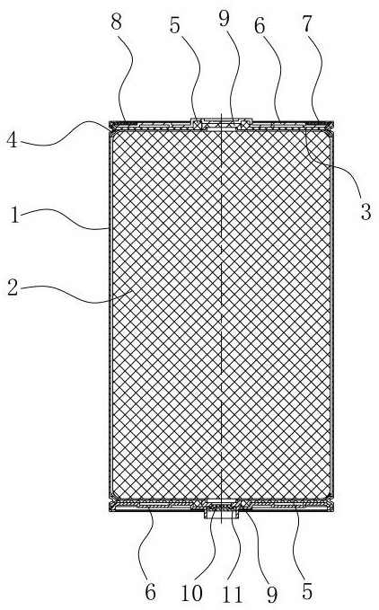
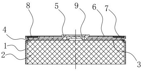
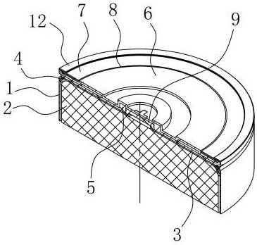
[0039] Such as Figure 1~Figure 15 As shown, 1. Shell, 2. Cell, 3. Current collector, 31. Liquid injection hole, 32. Convex ring, 4. Insulation ring, 5. Seal ring, 6. Cap, 61. Blind hole, 62. Cover hole, 63. Inner crimping, 7. Conductive support ring, 8. Ring sealing ring, 9. Collecting cap, 91. Cone seal, 92. Collecting hole, 10. Explosion-proof sealing cover, 11. Negative cap, 12. Outer crimping, 13. Rolling groove.

[0040] A lithium battery terminal structure and manufacturing method, such as figure 1 As shown, it has two structural forms, the first structural form is as figure 2 , image 3 As shown, this structural form can only be used as the positive end, and the second structural form is as image 3 , Figure 4 As shown, this structural form can be used as both the negative terminal and the positive terminal. Therefore, in a lithium batt...


PUM


Abstract

The invention discloses a lithium battery end structure and a manufacturing method, the lithium battery end structure comprises a shell, a battery cell, a current collector and the like, a current collector cap and a sealing ring sleeved outside the current collector cap are arranged outside the current collector, the current collector cap covers a liquid injection hole of the current collector and is conductively connected with the current collector, an inner circumference seal is formed between the sealing ring and the current collector cap. Outer circumferential sealing is formed between the sealing ring and the shell, a cover cap is arranged outside the sealing ring and the current collecting cap, the cover cap and the current collecting cap are in conductive connection, and the outer edge of the cover cap is peripherally pressed and conductively fixed by an outer turned edge at the end part of the shell; obviously, the port structure of the whole shell also achieves the conductive sealing effect under the condition of fewer parts, and has the use advantages of simple structure, compact design, capability of better improving the capacity of the lithium battery, simplification of the automatic processing procedure and the like; Meanwhile, the outer turned edge is circumferentially pressed and conductively fixed, so that the structural connection strength is improved, the structural compactness is ensured, and the use is safer.

Description

technical field [0001] The invention relates to a structure for sealing the end of a lithium battery during the manufacturing process, in particular to an end structure and a manufacturing method of the lithium battery. Background technique [0002] At present, the end sealing is required in the production and manufacturing process of lithium batteries. The traditional way is to seal and install the current collecting plate at the end of the shell, so as to seal the battery cell and electrolyte in the shell, and then seal it in the current collecting plate. Various components such as collector rings, decorative rings, sealing rings and glands are set on the chip for conductive sealing. This kind of port structure design is too complicated and there are many parts, which will occupy more volume of the lithium battery, resulting in a reduction in the capacity of the lithium battery. ; At the same time, the overly complex structure also increases the production process and incr...

Claims


Application Information

Patent Timeline
IPC IPC(8): H01M50/107H01M50/152H01M50/167H01M50/184H01M50/186H01M50/528H01M50/531H01M50/545H01M50/636H01M10/052H01M10/058H01M4/70
CPCH01M50/107H01M50/152H01M50/186H01M50/184H01M50/636H01M50/531H01M50/167H01M50/545H01M50/528H01M10/052H01M10/058H01M4/70Y02E60/10Y02P70/50
Inventor 朱效铭
Owner 宁波久鼎新能源科技有限公司
Why Eureka
Try Eureka