Rapid positioning device for shearing of plate shearing machine
A positioning device and shearing machine technology, applied in the direction of shearing devices, shearing machine accessories, shearing machine equipment, etc., can solve the problems of occupying the shearing positioning space, unable to clean the plate in time, and inconvenient operation of shearing and fixing positions , to achieve the effect of ensuring the cutting quality
- Summary
- Abstract
- Description
- Claims
- Application Information
AI Technical Summary
Problems solved by technology
Method used
Image
Examples
Embodiment 1
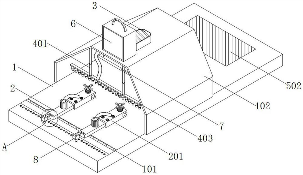
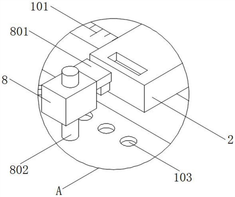
[0047] see figure 1 , image 3 , Figure 4 , Figure 7 and Figure 8 , a kind of embodiment that the present invention provides: a kind of plate shearing machine shears fast positioning device, comprises processing bottom plate 1 and positioning detection plate 7, and the top of processing bottom plate 1 is equipped with protective cover 102, and the inner top wall of protective cover 102 is installed There is a marking positioning structure 4, and the inner top wall of the protective cover 102 is equipped with a positioning detection plate 7, and the positioning detection plate 7 is located behind the marking positioning structure 4;
[0048] The bottom of the positioning detection board 7 is equipped with a photosensitive area 701, and the top side of the positioning detection board 7 is equipped with a strut, the surface of which is equipped with an angular velocity sensor 704, and a display screen 702 is installed on one side of the positioning detection board 7. And t...
Embodiment 2
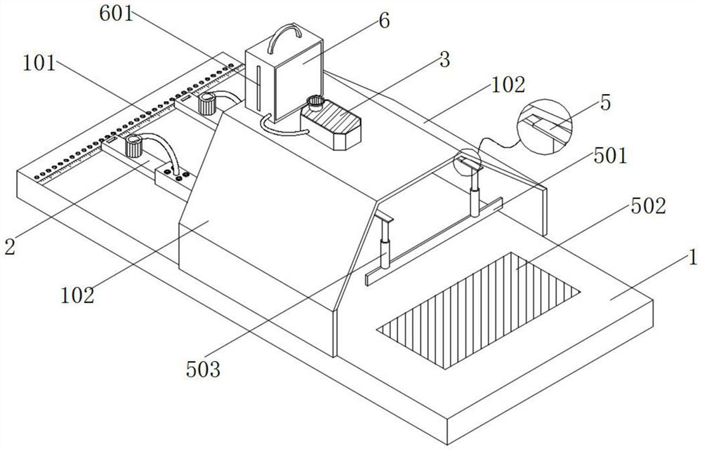
[0060] see figure 1 , figure 2 and Image 6, an embodiment provided by the present invention: a shearing machine shearing quick positioning device, including a spray box 6, the top of the protective cover 102 is equipped with a spray box 6, and one side surface of the spray box 6 A transparent observation strip 601 is installed, and a heating base plate 602 is installed on the inner bottom wall of the spray box body 6. A mixing box 604 is installed on the top of the heating base plate 602, and the inside of the mixing box 604 is filled with paint and flash powder. For the mixed liquid, an electronic viscometer 603 is installed through the top of the mixing box 604 , and the tail end of the electronic viscometer 603 extends to the inside of the mixing box 604 .
[0061] The top of protective cover 102 is equipped with suction pump 3, and the input end of suction pump 3 is connected with flexible pipe, and one end of flexible pipe extends into the inside of mixing box 604, an...
Embodiment 3
[0065] see figure 2 and Figure 9 , an embodiment provided by the present invention: a fast positioning device for shearing shears, including an electric push plate 5, an electric push plate 5 is installed on the inner top wall of the protective cover 102, and the electric push plate 5 is located on the positioning detection plate 7, the top surface of the processing bottom plate 1 is equipped with a pressure sensing plate 504, the top surface of the pressure sensing plate 504 is equipped with an isolation plate 502, and the isolation plate 502 is located behind the protective cover 102, and the bottom of the electric push plate 5 is equipped with a lift A rubber push plate 501 is installed on the bottom of the sleeve rod 503 and the lifting sleeve rod 503 , and the rubber push plate 501 is located above the isolation plate 502 .
[0066] Specifically, the cut plates are stacked on the surface of the processing base 1, and at this time, the electric telescopic plate 2 is sti...
PUM
 Abstract
Description
Claims
Application Information
 - R&D
- Intellectual Property
- Life Sciences
- Materials
- Tech Scout
- Unparalleled Data Quality
- Higher Quality Content
- 60% Fewer Hallucinations
Browse by: Latest US Patents, China's latest patents, Technical Efficacy Thesaurus, Application Domain, Technology Topic, Popular Technical Reports.
© 2025 PatSnap. All rights reserved.Legal|Privacy policy|Modern Slavery Act Transparency Statement|Sitemap|About US| Contact US: help@patsnap.com


