Oscillating jet type pressure pulse generating device
A technology of pressure pulse and generating device, which is applied in the direction of vibration generating device, drilling with vibration, wellbore/well components, etc. It can solve the problems of many vulnerable parts, limited service life, complex structure, etc., and achieve easy processing and manufacturing. Simple, easy to adjust frequency and fluctuation range
- Summary
- Abstract
- Description
- Claims
- Application Information
AI Technical Summary
Problems solved by technology
Method used
Image
Examples
Embodiment 1
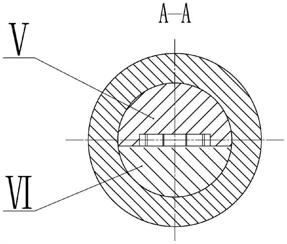
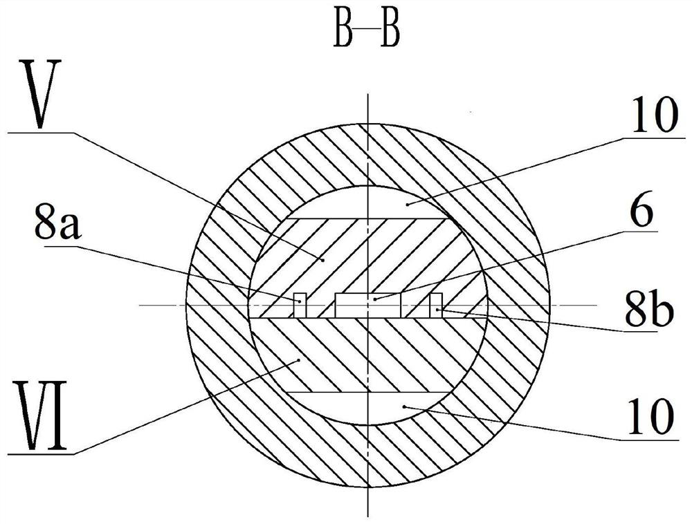
[0033] Such as Figure 1 to Figure 4 As shown, the embodiment of the present invention provides an oscillating jet pressure pulse generator, including: outer tube II, upper joint I, lower joint IV and vortex jet oscillator III, the upper joint I and lower joint IV The central fluid channel 1 of the upper joint and the central fluid channel 2 of the lower joint are respectively opened, and the two ends of the outer pipe II are respectively connected with the upper joint I and the lower joint IV through threads, and the vortex jet oscillator III is set at In the outer tube II, the two ends of the vortex jet oscillator III are connected to the upper joint I and the lower joint IV respectively, and the upper end of the vortex jet oscillator III is in contact with the upper joint I and passed through The sealing ring is sealed, the lower end of the vortex jet oscillator III is in contact with the lower joint IV and pressed tightly; the vortex jet oscillator III is provided with a j...
Embodiment 2
[0042] The structure of this embodiment is similar to that of Embodiment 1, the difference is that the special-shaped guide block 13, the second vortex cavity 14 and the second vortex cavity outlet 15 are added. In this embodiment, the fluid channel of the vortex jet oscillator III is set as follows Image 6 shown.
[0043] Compared with Embodiment 1, the vortex jet oscillator III of this embodiment adds a special-shaped guide block 13 and a second vortex chamber 14 sequentially below the vortex chamber 7, and the special-shaped guide block 13 will be connected with the substrate V and The cover plate VI forms a second left control channel 16a and a second right control channel 16b; a second vortex chamber outlet 15 is additionally added on the base plate V and the cover plate VI; as an improvement of this embodiment, the vortex chamber 7 and In the second vortex chamber 14 , an outlet of the vortex chamber can be re-set in at least one cavity to communicate with the emptying ...
Embodiment 3
[0047] The working principle of this embodiment is basically the same as that of the vortex jet oscillator III in Embodiment 2. Such as Figure 7 As shown, compared with Embodiment 2, the difference of this embodiment is that the shape of the special-shaped guide block 13 is changed, and a central control channel 17 is added on the special-shaped guide block 13, and the central control channel 17 communicates with The pressure waveform of the vortex chamber 7 and the second vortex chamber 14 in Embodiment 3 is as follows Figure 8 shown. According to different usage conditions, the outlet of the vortex chamber can also be selectively provided at the position of the vortex chamber 7 according to the actual situation. The vortex type oscillating jet pressure pulse generating device provided in this embodiment has the characteristics of low frequency and long pressure duration near the peak value, can form a nearly trapezoidal pressure pulse waveform, and has a high utilization...
PUM
 Abstract
Description
Claims
Application Information
 - R&D
- Intellectual Property
- Life Sciences
- Materials
- Tech Scout
- Unparalleled Data Quality
- Higher Quality Content
- 60% Fewer Hallucinations
Browse by: Latest US Patents, China's latest patents, Technical Efficacy Thesaurus, Application Domain, Technology Topic, Popular Technical Reports.
© 2025 PatSnap. All rights reserved.Legal|Privacy policy|Modern Slavery Act Transparency Statement|Sitemap|About US| Contact US: help@patsnap.com


