Muck discharging gate system of spiral conveyor of earth pressure balance shield machine

A technology of screw conveyor and earth pressure balance, which is applied in the direction of earth drilling, mining equipment, mining equipment, etc., can solve the problems of increased resistance of the slag discharge ram, spewing over the square ground, and poor flow of slag to achieve Reduce the flow speed and avoid the effect of gushing

Pending Publication Date: 2021-12-07
CCCC THIRD HARBOR ENG +1
View PDF0 Cites 0 Cited by
  • Summary
  • Abstract
  • Description
  • Claims
  • Application Information

AI Technical Summary

Problems solved by technology

The gate of the soil bin is divided by two gates on the left and right, and the opening is opened from the middle to both sides. The advantage is that the space occupied is small, but the muck is easy to deposit at the gate if the flow is not smooth, and it will be stuffed into the gap and easily jam the gate of the soil bin. switch
When the slag gate of the screw conveyor encounters gushing, the gushing silt acts on the gate plate of the slag gate, which increases the resistance of the slag gate and cannot be closed normally, which may easily cause excessive gushing and even ground collapse

Method used


Image

  • Muck discharging gate system of spiral conveyor of earth pressure balance shield machine
  • Muck discharging gate system of spiral conveyor of earth pressure balance shield machine
  • Muck discharging gate system of spiral conveyor of earth pressure balance shield machine

Examples


Embodiment Construction

[0038] The present invention will be further described below in conjunction with accompanying drawing.

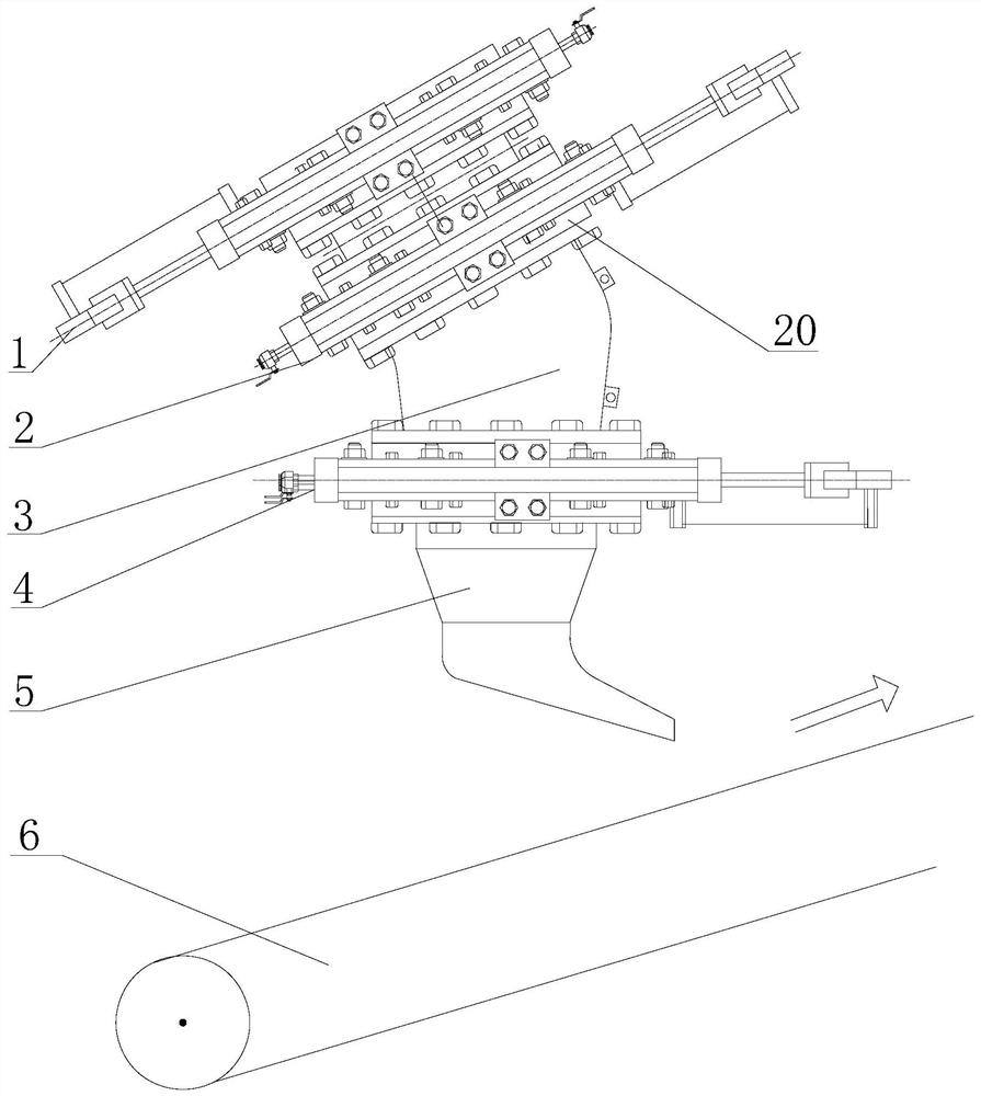
[0039] see Figure 1 to Figure 4 , the slag discharge gate system of the screw conveyor of the earth pressure balance shield machine of the present invention includes a first gate 1, a second gate 2, a slag discharge conduit 3, a Three gates 4 and slag hopper 5.

[0040] The structure and size of the first gate 1, the second gate 2 and the third gate 4 are the same; and the opening direction of the first gate 1 is opposite to the rotation direction of the belt conveyor 6, and the second gate 2 The opening direction of the gate is the same as the direction of rotation of the belt conveyor 6, and the opening direction of the third gate 4 is the same as that of the second gate 2.

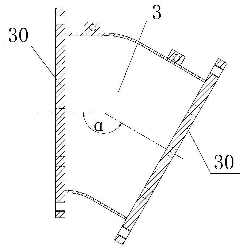
[0041] The slag discharge conduit 3 is arc-shaped and the angle α between the inlet end and the outlet end is 120°-160°; the inlet end and the outlet end of the slag discharge conduit 3 are also p...


PUM


Abstract

The invention discloses a muck discharging gate system of a spiral conveyor of an earth pressure balance shield machine. The muck discharging gate system comprises a first gate, a second gate, a muck discharging guide pipe, a third gate and a muck sliding funnel which are sequentially installed at a muck outlet of the spiral conveyor, each gate comprises a gate plate supporting frame, a gate plate, a pair of oil cylinder supports and two hydraulic oil cylinders, the gate plate supporting frame comprises a supporting frame body, a nylon guide groove and a sealing assembly, the gate plate comprises a gate plate body and a gate plate top, the pair of oil cylinder supports are fixed in the middles of the outer side faces of the two sides of the supporting frame body, the two hydraulic oil cylinders are installed on the pair of oil cylinder supports correspondingly, piston rods of the two hydraulic oil cylinders are connected to the two sides of the top of the gate plate through connecting mechanisms correspondingly, the included angle between the inlet end and the outlet end of the muck discharging guide pipe is 120-160 degrees, and the included angle between the inlet end and the outlet end of the muck slipping funnel is 100-130 degrees. According to the muck discharging gate system, the flowing speed of muck can be effectively reduced, and the gushing phenomenon of the shield tunneling machine in the tunneling process is avoided.

Description

technical field [0001] The invention relates to a slag discharge gate system of a screw conveyor of an earth pressure balance shield machine. Background technique [0002] The hydraulic motor of the shield machine drives the cutter head to rotate, and the muck cut off from the excavation face enters from the opening of the cutter head and falls to the bottom of the soil bin, and is transported to the slag discharge gate by the screw conveyor, and then discharged to the belt conveyor On the machine, the belt conveyor unloads the slag into the slag bucket truck parked on the track, and transports it to the slag outlet outside the cave, lifts it to the ground and pours it into the slag pit. [0003] During the construction of the earth pressure balance shield machine, if it encounters bedrock protrusions and weathered rock strata in the whole section, the crack water in the transition section between soft and hard uneven rock and soil is relatively developed, which will cause t...

Claims


Application Information

Patent Timeline
IPC IPC(8): E21D9/12E21F17/00
CPCE21D9/124E21F17/00
Inventor 陈顺天黄春来陈明才饶伟王建中陈细红
Owner CCCC THIRD HARBOR ENG
Why Eureka
Try Eureka