Boiler waste heat utilization device

A technology of boiler waste heat and heat exchange device, which is applied in heat exchangers, heat transfer modification, indirect heat exchangers, etc. The effect of thermal efficiency

Pending Publication Date: 2021-12-07
王伟
View PDF0 Cites 4 Cited by
  • Summary
  • Abstract
  • Description
  • Claims
  • Application Information

AI Technical Summary

Problems solved by technology

[0004] Aiming at the deficiencies of the prior art, the present invention provides a boiler waste heat utilization device, which solves the problem that the flue gas generated during the combustion process of the boiler is usually directly discharged into the outside air, and the heat carried in the flue gas will be discharged together with the flue gas. The problem that the heat in the flue gas cannot be effectively used when it is discharged to the outside

Method used


Image

  • Boiler waste heat utilization device
  • Boiler waste heat utilization device
  • Boiler waste heat utilization device

Examples


Embodiment 1

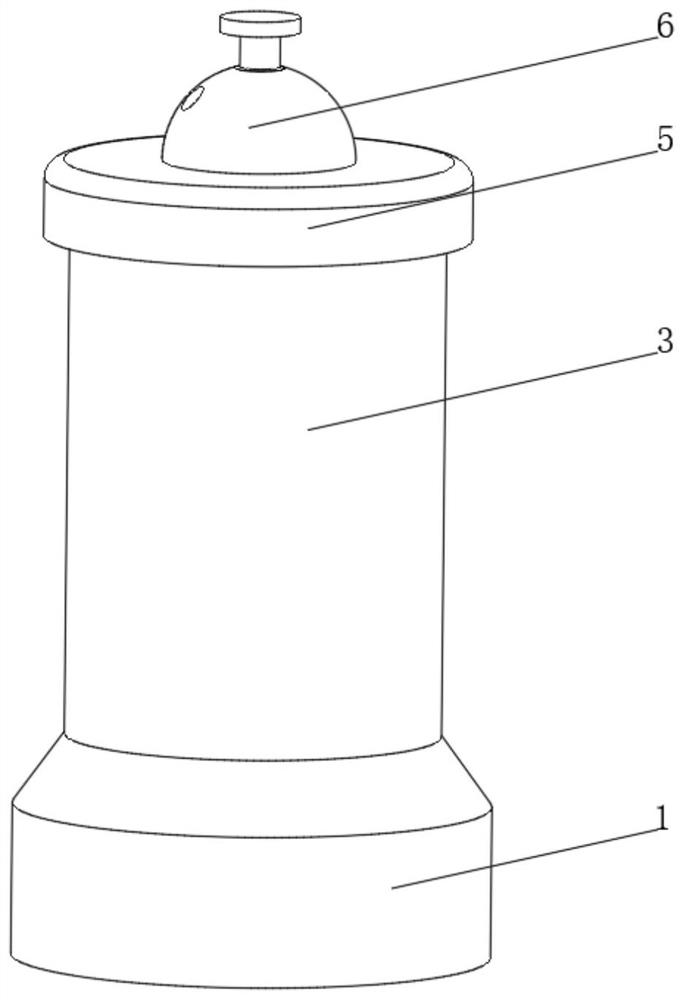
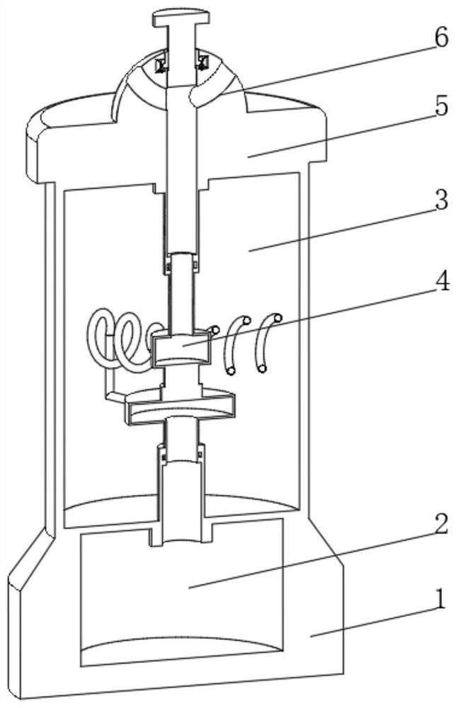
[0037] See Figure 1-3 The present invention provides a technical solution: a boiler waste heat utilization device, specifically includes:

[0038] Base 1, the rear space 2 is opened inside, and the heating space 2 is provided with a dispensing port;

[0039] The water storage cylinder 3 is disposed at the top of the base 1, and the heat exchange device 4 is provided inside the water storage cylinder 3, and the heat exchange device 4 is in communication with the bottom of the heating space 2;

[0040] The top cover 5 is provided at the top of the water storage cylinder 3, and the top cover 5 is disposed inside the top cover 5, and the adjustment device 6 is provided, and the adjustment device 6 is connected to the top of the heat exchange device 4;

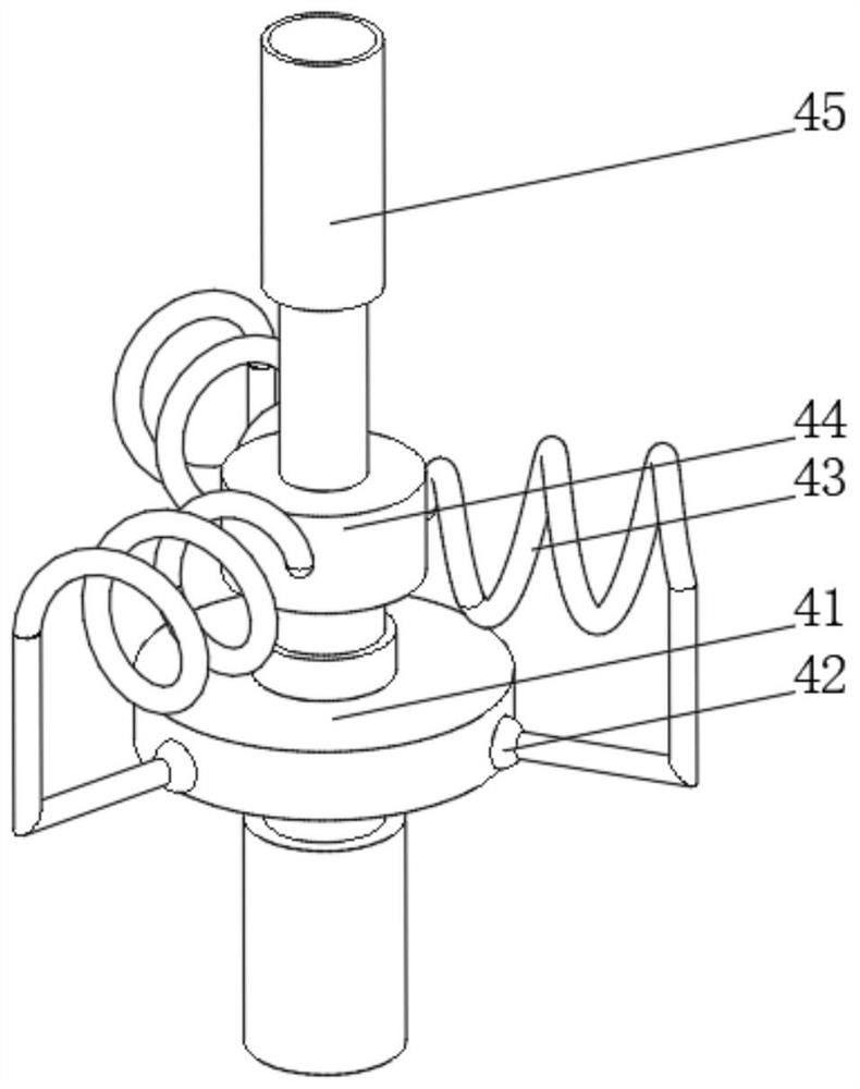
[0041] The heat exchange device 4 includes:

[0042] The split disk 41 is provided with a spiral heat transfer tube 43, a rotating device 42, and a helix heat transfer pipe 43, by the rotating device 42.

[0043] The gas disc 44, the b...

Embodiment 2

[0047] See Figure 1-4 Based on the example one, the present invention provides a technical solution: the rotating device 42 includes a rotating seat 421, and the inner wall of the rotating seat 421 is rotatably connected to the seal ball 422, and the sealing ball 422 is penetrated and fixed to the metal hose. 423. The rotating seat 421 is connected to the side of the seal ball 422 and the split disk 41, and the metal hose 423 is in communication with the helix heat transfer pipe 43, and a rotating device is provided, and the heat exchange device 4 is required to be maintained. Or replacement, the distance between the dividing disk 41 and the gas disc 44 can be shortened by controlling the telescopic rod between the split disk 41 and the gas disc 44, thereby taking it from the connecting pipe 45, convenient for later maintenance and Replacement parts.

Embodiment 3

[0049] See Figure 1-5 The present invention provides a technical solution in the present invention, and the adjustment device 6 includes a mount 61, and an airway 62 is opened inside the mount 61, and there is a vent 63 on both sides of the airway 62. The top of the airway 62 is threaded with a seal piston 64 by the thread sleeve 65, and the mount 61 is located on the portion of the thread sleeve 65, and the buckle groove 66 is opened, the buckle groove 66 is rotated to connect to the ball buckle 67, A curved spring is provided between the ball buckle 67 and the inner wall of the snap groove 66, and the mount 61 is disposed at the top of the water storage cylinder 3, and the airway 62 is connected to the connecting pipe 45 at the top of the gas disc 44, the thread sleeve 65 is located in the card The partial setting inside the buckle 66 is a snap ball 68 that is adapted to the ball head card buckle 67.

[0050] The adjustment device 6 is provided, and the inside of the adjustment ...


PUM


Abstract

The invention discloses a boiler waste heat utilization device which specifically comprises a base, a water storage barrel and a top cove, a heating space is formed in the base, and a smoke outlet is formed in the top of the heating space; the water storage barrel is arranged at the top of the base, a heat exchange device is arranged in the water storage barrel, and the bottom of the heat exchange device is communicated with a matched cornice at the top of the heating space; the top cover is arranged at the top of the water storage barrel, an adjusting device is arranged in the top cover, and the bottom of the adjusting device communicates with the top of the heat exchange device; the heat exchange device comprises a flow dividing disc, the side face of the flow dividing disc communicates with spiral heat exchange pipes through rotating devices, and the multiple sets of rotating devices and the multiple sets of spiral heat exchange pipes are arranged. The invention relates to the technical field of waste heat utilization. According to the boiler waste heat utilization device, heat in smoke can be used for conducting auxiliary heating on water, heat waste is avoided, boiler heating can be more uniform, and the heat exchange efficiency can be improved conveniently.

Description

Technical field [0001] The present invention relates to the field of waste heat utilization, and is specifically a boiler waste heat utilization device. Background technique [0002] After the heat is under certain economic and technical conditions, there is no energy used in energy utilization equipment, which is excessive, abandoned energy. It includes several types of high temperature exhaust gas, cooling medium waste heat, wastewater wastewater, high temperature products and slag waste heat, chemical reaction heat, flammable waste gas waste liquid and waste heat, and high pressure fluid, there are many ways, but mainly There are three aspects: the direct utilization of waste heat, the waste heat power generation, and the comprehensive utilization of waste heat. At present, the flue gas generated during the boiler is usually discharged directly into the outside air. The heat carried in the flue gas will be discharged to the outside, and the heat in the flue gas cannot be utili...

Claims


Application Information

Patent Timeline
Patent Type & Authority Applications(China)
IPC IPC(8): F23J15/06F28D21/00F28F13/12
CPCF23J15/06F28D21/0014F28F13/125Y02E20/30Y02B30/56
Inventor 王伟
Owner 王伟
Why Eureka
Try Eureka