Evaporation device used for heat pipe radiator

A heat pipe radiator and evaporating device technology, used in evaporators/condensers, lighting and heating equipment, refrigerators, etc., can solve the problems of waste of condensed water, inability to continuously participate in cooling, short paths, etc., and achieve uniform heat distribution. Effect

Active Publication Date: 2021-12-07
LAIWU VOCATIONAL & TECHNICAL COLLEGE
View PDF7 Cites 1 Cited by
  • Summary
  • Abstract
  • Description
  • Claims
  • Application Information

AI Technical Summary

Problems solved by technology

[0003] However, in the evaporative condenser in the prior art, the path of the heat exchange steam formed by the fan and spray water is relatively short, and the gaseous condensed water after absorbing heat is discharged with the air flow, which cannot continue to participate in the cooling process, resulting in condensation. Waste of water; so the present invention provides a kind of evaporation device for heat pipe radiator, to solve the above problems

Method used


Image

  • Evaporation device used for heat pipe radiator
  • Evaporation device used for heat pipe radiator
  • Evaporation device used for heat pipe radiator

Examples


Embodiment 1

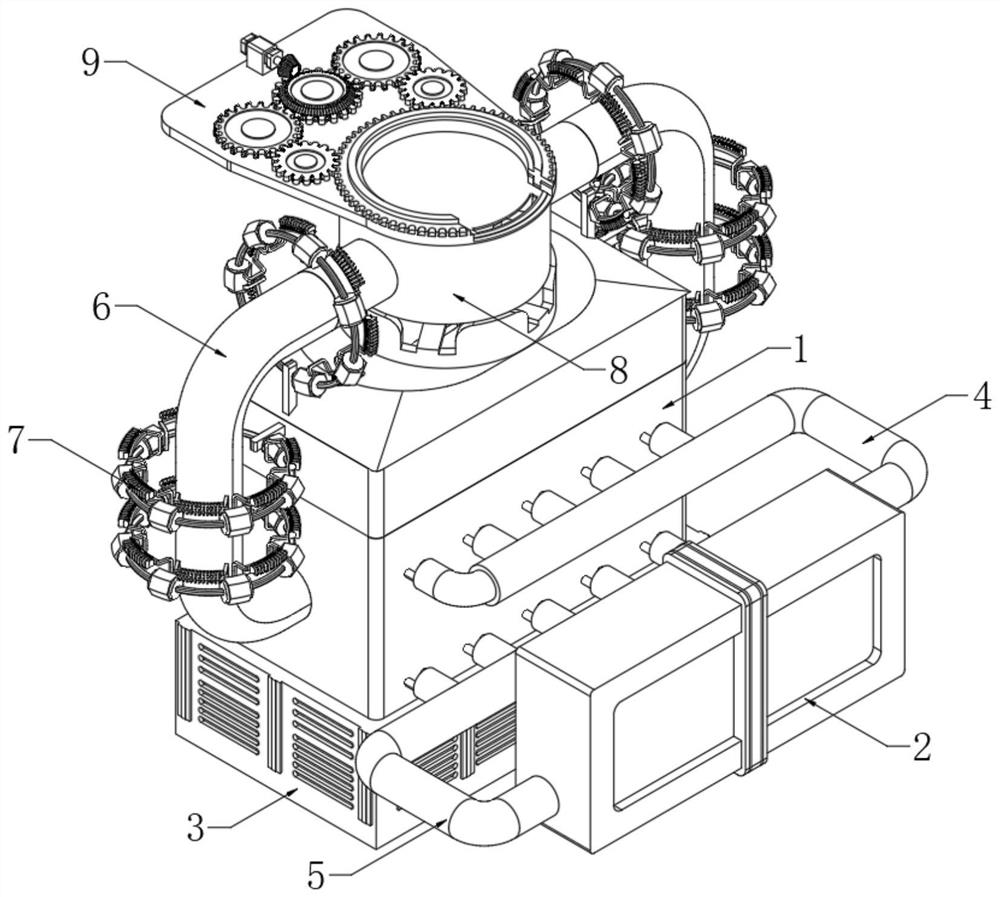
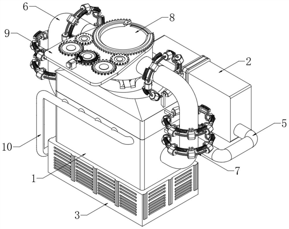
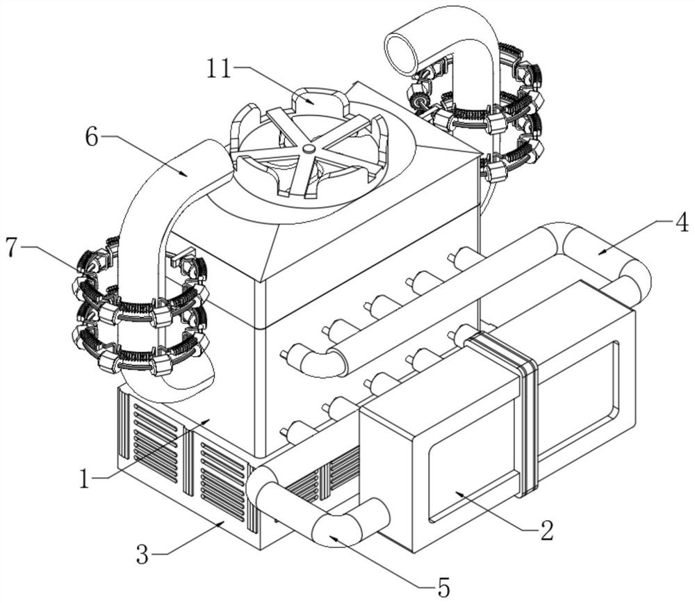
[0037] see Figure 1-6 , an evaporation device for a heat pipe radiator, comprising a cooling box 1, a condensate storage tank 3 is fixedly connected to the lower end of the cooling box 1, a driving water pump is arranged inside one side of the condensing water storage box 3, and the output end of the driving water pump is fixedly connected There is a spray pipe 10, the upper end of the spray pipe 10 is evenly connected with a plurality of spray pipes on the front side, and the end of the spray pipe is provided with a plurality of spray heads; the spray pipe 10 runs through the condensed water storage tank 3 and extends to the outside of the heat dissipation tank 1 At the upper end, the spray conduit at the front end of the spray pipe 10 runs through the upper side wall of the heat dissipation box 1; the fan 11 is fixedly connected to the center of the upper side of the heat dissipation box 1, and the circulation pipe 6 is fixedly connected to both sides of the heat dissipation...

Embodiment 2

[0041] Such as Figure 6-8 As shown, the differences based on Embodiment 1 are:

[0042] The cooling assembly 7 includes a mounting ring 701, the center of the mounting ring 701 is fixedly connected to the wall of the cooling box 1 through a mounting rod 706, and a plurality of positioning columns 702 are uniformly arranged on the mounting ring 701;

[0043] The outside of the positioning column 702 is rotatably connected with an overturning column 703, and one side of the overturning column 703 is rotatably connected with two U-shaped bars 707, and a connecting frame 704 is fixedly connected between the U-shaped bars 707 on two adjacent overturning columns 703, and the connecting frame The outer side of 704 is fixedly connected with a heat sink group 705;

[0044] One side near the mounting rod 706 is provided with a turning motor 708, and the mounting ring 701 is provided with an installation arc, and one end of the turning motor 708 is fixedly connected with the installati...

Embodiment 3

[0048] Such as Figure 9-12 , based on Embodiment 1-2, the difference is:

[0049] An exhaust pipe 8 is fixedly connected to the center of the upper end of the circulation pipe 6, and an intermittent exhaust assembly 9 is arranged on the upper side of the exhaust pipe 8. The intermittent exhaust assembly 9 includes a mounting plate 901, and the mounting plate 901 is fixedly connected to the upper end of the exhaust pipe 8;

[0050] The front end of the mounting plate 901 is fixedly connected with a connection plate 908, and the connection plate 908 is fixedly connected to the upper side of the exhaust pipe 8; the front side of the connection plate 908 is provided with an exhaust hole 909, and the upper side of the connection plate 908 is provided with a ring rail, which slides in the ring rail A gear ring 907 is connected; the lower side of the gear ring 907 is fixedly connected with a sealing ring 911, the surface of the sealing ring 911 is provided with a rubber layer, and t...


PUM


Abstract

The invention discloses an evaporation device used for a heat pipe radiator, and belongs to the technical field of radiators. The evaporation device used for the heat pipe radiator comprises a heat dissipation box, the lower end of the heat dissipation box is fixedly connected with a condensate water storage box, a driving water pump is arranged in one side of the condensate water storage box, the output end of the driving water pump is fixedly connected with a spraying pipe, the front side of the upper end of the spraying pipe is evenly connected with multiple spraying guide pipes, and multiple spraying heads are arranged at the tail ends of the spraying guide pipes; the spraying pipe penetrates through the condensate water storage box and extends to the upper end of the outer portion of the heat dissipation box, and the spraying guide pipes at the front end of the spraying pipe penetrate through the side wall of the upper end of the heat dissipation box; and a fan is fixedly connected to the center of the upper side of the heat dissipation box, and circulating pipes are fixedly connected to the two sides of the heat dissipation box. The evaporation device solves the problem that in the prior art, gaseous condensate water after heat absorption is discharged along with airflow and cannot continuously participate in the circulating cooling process.

Description

technical field [0001] The invention relates to the technical field of radiators, in particular to an evaporation device for heat pipe radiators. Background technique [0002] The evaporative condenser is a heat exchange device used for cooling the cold storage. It is composed of a fan, a condensation coil, a heat exchange fin, a box and other components; When part of the spray water evaporates, it absorbs the heat of the high-temperature gaseous refrigerant in the coil so that the refrigerant in the tube is gradually cooled from the gaseous state to the liquid state. [0003] However, in the evaporative condenser in the prior art, the path of the heat exchange steam formed by the fan and spray water is relatively short, and the gaseous condensed water after absorbing heat is discharged with the air flow, which cannot continue to participate in the cooling process, resulting in condensation. Waste of water; so the present invention provides an evaporation device for heat pi...

Claims


Application Information

Patent Timeline
IPC IPC(8): F25B39/04
CPCF25B39/04F25B2339/041
Inventor 唐修金付贵臣
Owner LAIWU VOCATIONAL & TECHNICAL COLLEGE
Why Eureka
Try Eureka