Sampling device for soil detection
A sampling device and soil detection technology, applied in the agricultural field, can solve the problems of reducing soil efficiency, inaccurate detection effect, inconvenient soil sampling, etc., and achieve the effects of improving efficiency, reducing labor, and increasing convenience and practicability.
- Summary
- Abstract
- Description
- Claims
- Application Information
AI Technical Summary
Problems solved by technology
Method used
Image
Examples
Embodiment 1
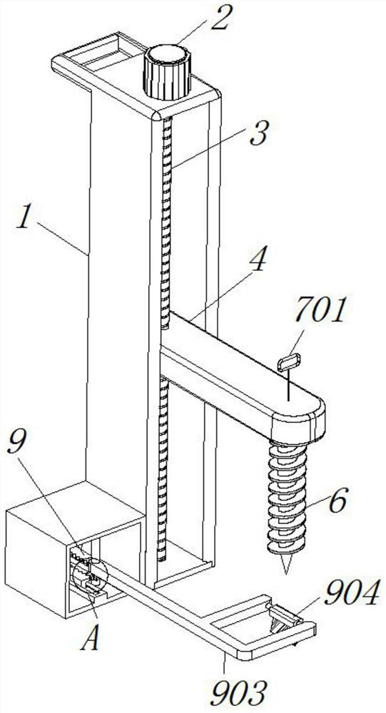
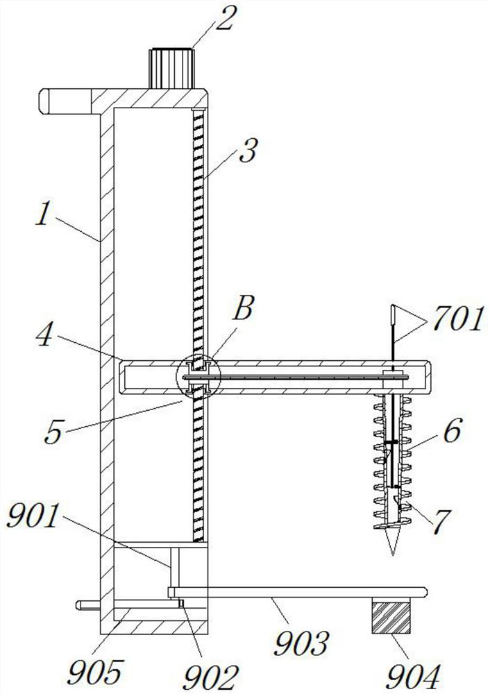
[0033] see Figure 1-2 and Figure 4 , the weeding mechanism 9 includes a rotating shaft 901 bearing connected to the lower front side of the housing bracket 1, and a transmission gear 902 is fixed on the outside of the rotating shaft 901, and a rotating plate 903 is welded on the outside of the rotating shaft 901, and a weeding rake 904 is fixed inside the right side of the rotating plate 903 , the front and rear sides of transmission gear 902 are all meshed with movable rack plate 905, the bottom of weeding rake 904 is in contact with the soil surface, the bottom of movable rack plate 905 and the bottom of shell bracket 1 are sliding structures, and the two movable racks are reciprocated with feet earlier. The rack plate 905 is pushed, so that the movable rack plate 905 slides left and right at the inner bottom of the lifting housing 4, and under the left and right movement of the movable rack plate 905, the transmission gear 902, the rotating shaft 901 and the rotating plat...
Embodiment 2
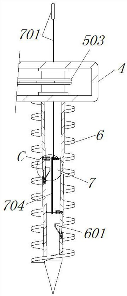
[0035] see Figure 2-3 and Figure 5-6 The difference from Embodiment 1 is that the upper and lower inner walls of the lifting housing 4 are provided with chute 401, and the lifting and rotating mechanism 5 includes a runner 501 engaged in the inner side of the chute 401, and the outer side of the runner 501 is keyed with a first The sprocket mechanism 502, the inside of the right side of the first sprocket mechanism 502 is keyed to the outside of the top of the soil drill bit 6, the left and right inner walls of the soil drill bit 6 are welded with fixed cylinders 601, and the bottom of the two fixed cylinders 601 are provided with receiving grooves 602, The conveying auger 702 cooperates with the torsion spring 703 to pull upward through the pull rope 701 to form a rotary soil fetching. First, the servo motor 2 is started to drive the screw shaft 3 to rotate, and the rotation of the screw shaft 3 drives the lifting shell 4 to cooperate with the shell bracket 1 to lift. ,Suc...
Embodiment 3
[0037] see image 3 and Figure 6 , the difference from Embodiment 2 is that the mechanism sampling mechanism 8 includes a slide block 801 that is engaged on the left and right inner walls of the soil drill bit 6, and a return spring 802 is installed below the slide block 801, and the slide block 801 is buckled with fingers, and cooperates with the The return spring 802 presses down, and then use a small digging spoon to take out the soil inside the receiving groove 602 for detection.
[0038] The working principle of the present invention is: as Figure 1-2 and Figure 4 As shown, first the whole device is manually placed in the designated place, and then the two movable rack plates 905 are pushed back and forth with the feet, so that the movable rack plates 905 slide left and right at the bottom of the inner side of the lifting housing 4, and the movable rack plates 905 slide left and right at the bottom of the inner side of the lifting housing 4. Under the left and right...
PUM
 Abstract
Description
Claims
Application Information
 - R&D
- Intellectual Property
- Life Sciences
- Materials
- Tech Scout
- Unparalleled Data Quality
- Higher Quality Content
- 60% Fewer Hallucinations
Browse by: Latest US Patents, China's latest patents, Technical Efficacy Thesaurus, Application Domain, Technology Topic, Popular Technical Reports.
© 2025 PatSnap. All rights reserved.Legal|Privacy policy|Modern Slavery Act Transparency Statement|Sitemap|About US| Contact US: help@patsnap.com


