Laser radar debugging device and debugging method

A technology of laser radar and debugging method, applied in the direction of measuring device, re-radiation of electromagnetic waves, utilization of re-radiation, etc., can solve the problems of great difficulty, poor productivity, long debugging time, etc., to reduce the number of debugging, improve efficiency and debugging. easy effect

Active Publication Date: 2021-12-07
宁波未感半导体科技有限公司
View PDF11 Cites 1 Cited by
  • Summary
  • Abstract
  • Description
  • Claims
  • Application Information

AI Technical Summary

Problems solved by technology

However, semiconductor lasers have the following disadvantages: the performance is greatly affected by temperature, the divergence angle of the beam is large (generally between a few degrees and 20 degrees, and there is astigmatism between the fast axis and the slow axis of the semiconductor laser, the fast axis and the slow axis There is a big difference in the divergence angle, the divergence angle in the fast axis direction is much larger than the divergence angle in the slow axis direction), so it is poor in directionality, monochromaticity and coherence.
[0003] The existing laser radar launch and debugging scheme in the industry mainly adopts that multiple semiconductor lasers are placed on a circuit board, and multiple circuit boards are placed side by side at the same time. Each circuit board is independently movable, so it can effectively solve the laser problem. The resolution of the vertical field of view of the radar is too low. However, each circuit board needs to be debugged independently. When the field of view of the lidar is large and the vertical resolution is high, more circuit boards need to be debugged. , resulting in long debugging time and great difficulty; and because there are too many movable parts, it is difficult to fix after debugging, and each movable part needs to be fixed, and the productivity is poor

Method used


Image

  • Laser radar debugging device and debugging method
  • Laser radar debugging device and debugging method
  • Laser radar debugging device and debugging method

Examples


Embodiment 1

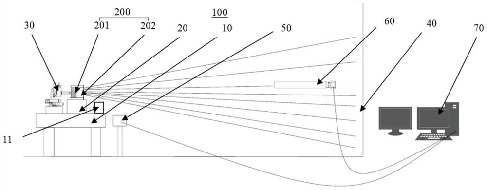
[0037] see figure 1 , an embodiment of the present application provides a lidar debugging device 100 . The laser radar debugging device 100 is used for debugging the azimuth and divergence angle of the laser radar transmitter 200 to ensure the ranging distance and ranging accuracy of the laser radar 200 .

[0038] The lidar transmitter 200 includes a laser group 201 and a laser lens group 202 . The laser lens group 202 is used for collimating the laser light emitted by the laser group 201 .

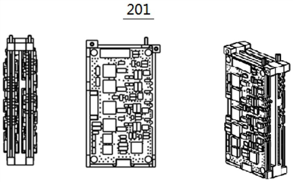
[0039] Such as figure 2 As shown, in this embodiment, the laser group 201 is a multi-line semiconductor emitting assembly. According to the pre-design, a plurality of semiconductor laser diodes are accurately distributed in the emitting assembly, and the position of each semiconductor laser diode is precisely processed according to the design. , for better heat dissipation.

[0040]Since the semiconductor laser diode is the same part, the divergence angle of each laser beam is the sa...

Embodiment 2

[0064] see Figure 1 to Figure 6 , a laser radar debugging device 100 provided in this embodiment can be used for debugging the laser radar transmitting end 200 . This embodiment is an improvement made on the technical basis of the above-mentioned embodiment 1. Compared with the above-mentioned embodiment 1, the difference lies in:

[0065] Such as Image 6 As shown, the divergence angle measuring mechanism 60 includes a lens barrel 61 , an attenuation sheet 62 , a doublet lens 63 , a filter 64 and an industrial camera 65 . The attenuation sheet 62 , the doublet lens 63 , the optical filter 64 and the industrial camera 65 are sequentially arranged in the lens barrel 61 . The attenuation sheet 62 attenuates the laser light entering the lens barrel 61 to the range that the industrial camera 65 can withstand, and the optical filter 64 filters the surrounding ambient light to provide a low background noise working environment for the detection of the industrial camera 65 .

[...

Embodiment 3

[0073] see Figure 1 to Figure 6 , this embodiment also provides a debugging method for debugging the laser radar transmitter 200, so that the ranging distance and ranging accuracy of the laser radar 200 are improved. The debugging method of this embodiment is completed based on the laser radar debugging device 100 provided in the above-mentioned embodiments. The debugging methods include:

[0074] S101: Provide a lidar debugging device 100.

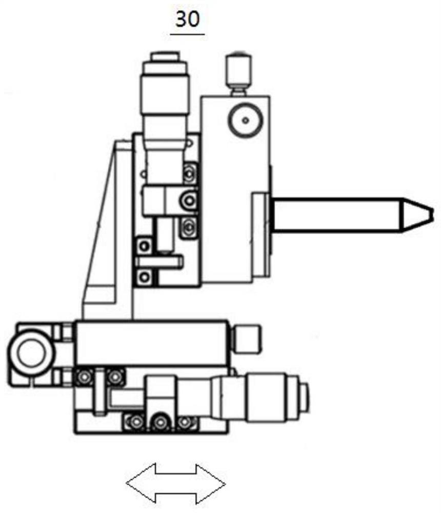
[0075] Specifically, the relative positions among the debugging platform 10 , the fixing bracket 20 and the adjusting bracket 30 are fixed, and the fixing bracket 20 and the debugging platform 10 are kept horizontal. The test board 40 is set relative to the debugging platform 10 , and the relative position is fixed. The relative position between the camera 50 and the test board 40 is fixed.

[0076] S102: Put the laser radar transmitter 200 with commissioning in the laser radar debugging device 100 .

[0077] Specifically, the laser...


PUM


Abstract

The invention provides a laser radar debugging device and a debugging method, relates to the technical field of laser radars. The device and method are used for debugging a laser radar transmitting end comprising a laser group and a laser lens group, and semiconductor laser diodes are distributed on the laser group. The laser radar debugging device comprises a debugging table, a fixing support, an adjusting support, a testing plate, a shooting device, a divergence angle measuring mechanism and a processing mechanism; the fixing support is used for fixing a laser lens group, the adjusting support is used for adjusting the laser lens group, the testing plate is arranged relative to the debugging table, and a reference mark is drawn on the testing plate. The shooting device is used for shooting the test plate, the divergence angle measuring mechanism is used for measuring a laser beam collimated by the laser lens group, and the processing mechanism is used for displaying measurement results of the shooting device and the divergence angle measuring mechanism and determining an adjustment result. The laser radar debugging device and method can adjust the azimuth angle and the divergence angle at the same time, debugging is easy and convenient, and the debugging efficiency is improved.

Description

technical field [0001] The invention relates to the technical field of laser radar, in particular to a laser radar debugging device and a debugging method. Background technique [0002] With the development of optoelectronic technology, lidar is more and more widely used in scenarios such as automatic driving, surveying and mapping, robot navigation, and space modeling. At the same time, the requirements for ranging capabilities of lidar are getting higher and higher. Most of the mechanical laser radars currently used for autonomous driving are based on the principle of pulsed laser ranging, and most of the lasers used are semiconductor lasers. Semiconductor lasers are small in size, light in weight, safe in use, and low in maintenance costs, so their application fields are expanding day by day. However, semiconductor lasers have the following disadvantages: the performance is greatly affected by temperature, the divergence angle of the beam is large (generally between a fe...

Claims


Application Information

Patent Timeline
Patent Type & Authority Applications(China)
IPC IPC(8): G01S7/497G01S17/931
CPCG01S7/497G01S17/931
Inventor 丁志田陈浩严伟振
Owner 宁波未感半导体科技有限公司
Why Eureka
Try Eureka