[0026] The following will clearly and completely describe the technical solutions in the embodiments of the present invention with reference to the accompanying drawings in the embodiments of the present invention. Obviously, the described embodiments are only some, not all, embodiments of the present invention. Based on the embodiments of the present invention, all other embodiments obtained by persons of ordinary skill in the art without making creative efforts belong to the protection scope of the present invention.
[0027] In the present invention, unless otherwise clearly specified and limited, terms such as "installation", "connection", "connection" and "fixation" should be understood in a broad sense, for example, it can be a fixed connection or a detachable connection , or integrated; it can be mechanically connected or electrically connected; it can be directly connected or indirectly connected through an intermediary, and it can be the internal communication of two components or the interaction relationship between two components. Those of ordinary skill in the art can understand the specific meanings of the above terms in the present invention according to specific situations.
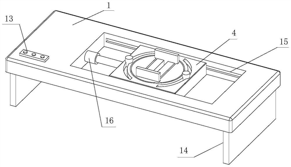
[0028] see Figure 1-6 , the present invention provides a technical solution: a clamping device for the front support frame accessories of the UAV, including a workbench 1, a clamping mechanism 2, an adjustment mechanism 3 and a fixed platform 5, and the inside of the workbench 1 is provided with a movable seat 4 , the fixed platform 5 is arranged inside the movable base 4 , the clamping mechanism 2 is arranged at the bottom of the fixed platform 5 , and the adjusting mechanism 3 is arranged inside the movable base 4 .
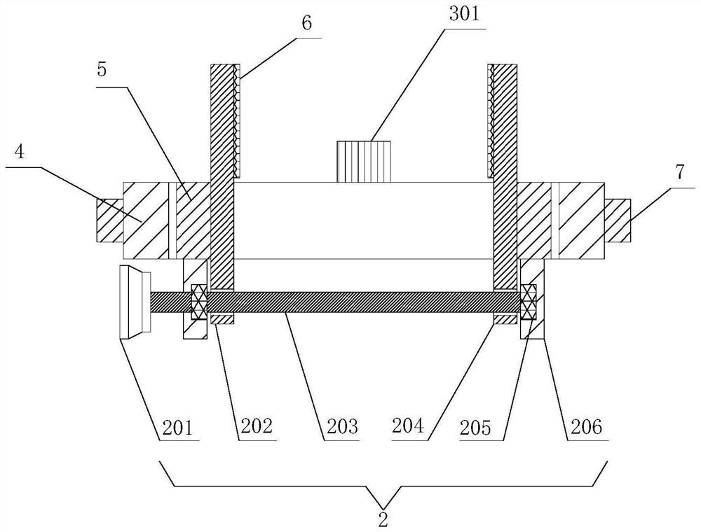
[0029] The clamping mechanism 2 includes a fixed plate 206 and a first bearing 205. The first bearing 205 is fixedly installed on the left side of the fixed plate 206. The inner rotation of the first bearing 205 is connected with a screw 203, and the rod body of the screw 203 is screwed with a second A splint 202 , a second splint 204 is threadedly connected to the rod body of the lead screw 203 .
[0030] The adjustment mechanism 3 includes a connecting plate 305 and a second bearing 304, the second bearing 304 is fixedly mounted on the upper surface of the connecting plate 305, the inner rotation of the second bearing 304 is connected with a threaded rod 303, and the top of the threaded rod 303 is threadedly connected with a fixed block 301.
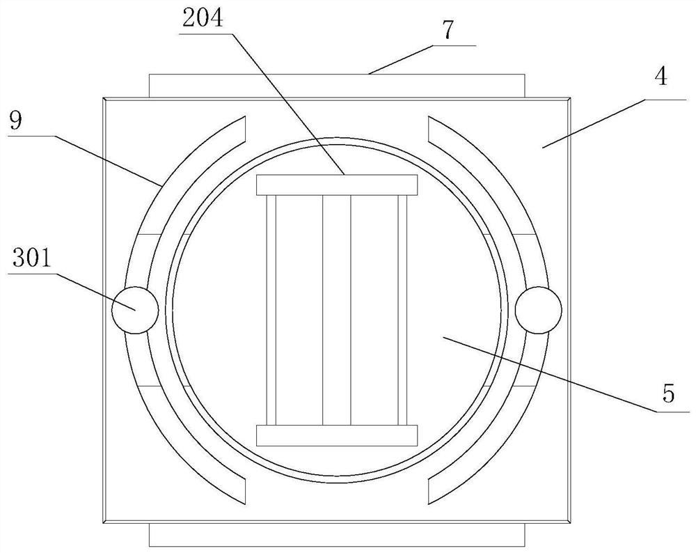
[0031]The inner lower end of the first clamping plate 202 is provided with a first internally threaded hole, and the screw mandrel 203 is threaded inside the first internally threaded hole, and the inner lower end of the second clamping plate 204 is provided with a second internally threaded hole, and the screw mandrel 203 is threadedly connected to the inside of the first internally threaded hole. Inside the second internally threaded hole, the internal thread direction of the first internally threaded hole is opposite to that of the second internally threaded hole, and the front end of the screw mandrel 203 is fixedly equipped with a handwheel 201. The internal threads of the screw are set as opposite threads. When the screw rod 203 rotates, it can drive the first splint 202 and the second splint 204 to approach each other or move away from each other, which is convenient for clamping and fixing the front bracket accessories of the drone. The fixing plate 206 is fixedly installed on the The bottom of the fixed table 5, the back side of the first splint 202 is bonded with a rubber pad 6, the upper surface of the fixed table 5 is provided with a moving port 10, the lower end of the first splint 202 runs through the inside of the movable port 10, and the lower end of the second splint 204 Through the inside of the moving port 10, the setting of the rubber pad 6 can increase the friction force when the first splint 202 contacts the accessories, so that the accessories are clamped more firmly, and at the same time, the rubber pad 6 can also protect the accessories. To avoid scratches on the accessories and the first splint 202, resulting in scratches on the accessories, further improving the practicability of the accessories clamping device, the upper surface of the fixed table 5 is provided with a chute 11, and the inner sliding connection of the chute 11 has Slider 12, slider 12 is fixedly mounted on the bottom of the second splint 204, the inside of fixed block 301 is provided with internally threaded hole 302, threaded rod 303 is threaded inside the inside of internally threaded hole 302, its slider 12 and chute 11 The setting of the second splint 204 can play a position-limiting effect, and at the same time it can facilitate the directional movement of the second splint 204 on the fixed table 5. The number of the chute 11 is two, and the two chute 11 are respectively opened on the fixed table 5. On the left side of the upper surface and the right side of the upper surface of the platform 5, the number of sliders 12 is two, and the two sliders 12 are respectively fixedly installed on the left side and the right side of the bottom of the second splint 204. The setting of the chute 11 It can facilitate the movement of the splint. The inside of the moving seat 4 is provided with an adjustment chute 8, and the connecting plate 305 is slidably connected to the inside of the adjustment chute 8. The upper surface of the moving seat 4 is provided with an adjustment slide 9, and the threaded rod 303 runs through the adjustment slide. mouth 9, the quantity of the adjustment sliding opening 9 is two, and its two adjustment sliding openings 9 are opened on the left side of the upper surface and the right side of the upper surface of the mobile seat 4 respectively, and the connecting plate 305 is fixedly installed on the side wall of the fixed table 5, Adjusting the setting of chute 8 and connecting plate 305 can play the effect of limit to fixed platform 5, also facilitates the angle adjustment of fixed platform 5 simultaneously, the inwall of workbench 1 offers limit chute 15, and the limit chute 15 The slide plate 7 is slidingly connected inside, and the slide plate 7 is fixedly mounted on the back side of the mobile seat 4. There are two limit chute 15, and the two limit chute 15 are respectively set on the inner front wall and the inner rear of the workbench 1. Wall, the setting of limit chute 15 and slide plate 17 can play the effect of position limit to mobile seat 4, also facilitates mobile seat 4 to move simultaneously, the bottom of workbench 1 is fixedly equipped with support plate 14, the quantity of support plate 14 for two, its Two support plates 14 are fixedly installed on the bottom left end and the bottom right end of the workbench 1 respectively, and a hydraulic cylinder 16 is fixedly installed inside the workbench 1, and the telescopic end of the hydraulic cylinder 16 is fixedly installed on the left wall of the mobile seat 4. A control panel 13 is fixedly installed on the upper surface of the upper surface, and the setting of the support plate 14 can support and fix the workbench 1. The hydraulic cylinder 16 can be activated to push the movable seat 4 to move, so as to facilitate the adjustment of the position of the movable seat 4 and the fixed platform 5. Adjustment, by placing the bracket accessories on the upper surface of the fixed table 5, the staff turns the hand wheel 201 to drive the screw mandrel 203 to rotate, because the internal threads of the first internal thread hole and the second internal thread hole are set to opposite threads, when When the screw mandrel 201 rotates, it can drive the first splint 202 and the second splint 204 to approach each other or move away from each other, which can facilitate the clamping and fixing of the front bracket accessories of the drone. The friction force when in contact with the accessories makes the accessories clamped more firmly. At the same time, its rubber pad 6 can also protect the accessories to avoid scratches between the accessories and the first splint, resulting in scratches on the accessories. Through The staff turns the fixed block 301 to move the fixed block 301 upward along the threaded rod 303. At this time, the fixed table 5 can be manually rotated, and the staff can adjust the fixed table 5 according to the angle of the accessory processing. After completion, the staff rotates in the opposite direction The fixed block 301 makes the fixed block 301 move down along the threaded rod 303, contacts the upper surface of the moving seat 4, and positions the fixed table 5. The structure is simple, and the angle of the fixed table 5 can be adjusted conveniently, so that accessories can be positioned at different angles. Processing improves the practicability of the clamping device. By starting the hydraulic cylinder 16, the movable seat 4 can be pushed to move along the limit chute 15, and the staff can adjust the position of the movable seat 4 according to the work requirements, so as to achieve the adjustment of the fixed table 5. The location makes the clamping device of the accessories more flexible and facilitates the production and processing of the front bracket accessories of the UAV.
[0032] In the actual operation process, when the device is in use, by placing the bracket accessories on the upper surface of the fixed table 5, the staff turns the hand wheel 201 to drive the screw rod 203 to rotate, because the first internal thread hole and the second internal thread The inner thread of the hole is set as the opposite thread, when the screw rod 201 rotates, it can drive the first splint 202 and the second splint 204 to approach or move away from each other, which can facilitate the clamping and fixing of the front bracket accessories of the drone. The setting of the pad 6 can increase the friction force when the first splint 202 is in contact with the accessories, so that the accessories are clamped more firmly, and at the same time, the rubber pad 6 can also protect the accessories to avoid scratches between the accessories and the first splint , leading to the phenomenon of scratches on the accessories, the fixed block 301 moves upward along the threaded rod 303 by the staff turning the fixed block 301, at this time the fixed table 5 can be manually rotated, and the staff can adjust the fixed table according to the angle of the accessories processing 5. After the completion, the staff rotates the fixed block 301 in the opposite direction, so that the fixed block 301 moves down along the threaded rod 303, contacts the upper surface of the moving seat 4, and positions the fixed table 5. The structure is simple and the fixed table can be adjusted conveniently The angle of 5 is convenient for accessories to be processed at different angles, and the practicability of the clamping device is improved. By starting the hydraulic cylinder 16, the movable seat 4 can be pushed to move along the limit chute 15, and the staff can adjust the movable seat according to the work requirements. 4, so as to adjust the position of the fixing table 5, make the clamping device of the accessories more flexible, and facilitate the production and processing of the front bracket accessories of the drone.
[0033] It should be noted that in this article, relational terms such as first and second are only used to distinguish one entity or operation from another entity or operation, and do not necessarily require or imply that there is a relationship between these entities or operations. There is no such actual relationship or order between them. Furthermore, the term "comprises", "comprises" or any other variation thereof is intended to cover a non-exclusive inclusion such that a process, method, article, or apparatus comprising a set of elements includes not only those elements, but also includes elements not expressly listed. other elements of or also include elements inherent in such a process, method, article, or device. Without further limitations, an element defined by the phrase "comprising a ..." does not exclude the presence of additional identical elements in the process, method, article or apparatus comprising said element.
[0034] Although the embodiments of the present invention have been shown and described, those skilled in the art can understand that various changes, modifications and substitutions can be made to these embodiments without departing from the principle and spirit of the present invention. and modifications, the scope of the invention is defined by the appended claims and their equivalents.