
Double-spindle symmetrical type grinding machining device

A grinding, symmetrical technology, applied in the field of grinding, can solve the problems of low work efficiency, the grinding machine fixture cannot meet the needs of production, and high processing costs, and achieve the effect of avoiding accuracy

Inactive Publication Date: 2021-12-10
杭州谦泰五金机械制造有限公司
View PDF9 Cites 0 Cited by
  • Summary
  • Abstract
  • Description
  • Claims
  • Application Information

AI Technical Summary

Problems solved by technology

[0003] The grinding angle of the current grinding machine is fixed, and the angle of the grinding machine fixture is also fixed, so a pair of grinding machine fixture can only process workpieces of the same specification, which is not universal, and for some molds Workpieces, such as crankshaft connecting rods, usually need to be ground on both sides of the surface. Grinding such workpieces needs to be carried out sequentially on multiple grinding machine fixtures with specific processing angles. Obviously, the grinding process of this kind of grinding machine fixtures The work efficiency is low and the processing cost is high
[0004] In the prior art, although there are grinding machine fixtures, there is no device that can simultaneously realize that a pair of grinding machine fixtures can be applied to workpieces of multiple specifications, which means that the existing grinding machine fixtures can no longer meet the production needs. Therefore, it is necessary to address The disadvantage of the existing technology is to design a dual-spindle symmetrical grinding device that can grind workpieces of different specifications and can fully grind multiple specific processing angles of the workpiece

Method used


Image

  • Double-spindle symmetrical type grinding machining device
  • Double-spindle symmetrical type grinding machining device
  • Double-spindle symmetrical type grinding machining device

Examples


Embodiment 1

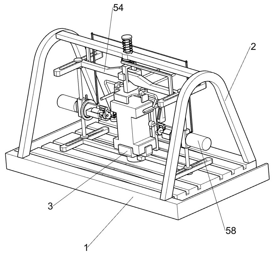
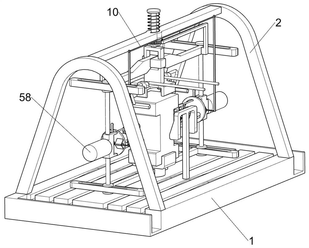
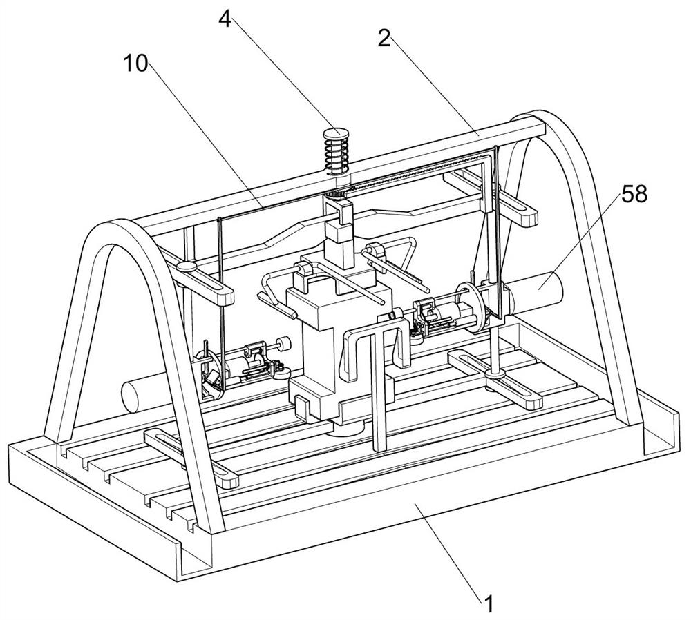
[0034] Symmetrical two-spindle grinding apparatus, such as figure 1 , figure 2 , image 3 , Figure 4 , Figure 5 , Image 6 , Figure 7 , Figure 8 , Figure 9 , Figure 10 and Figure 11 Shown, comprising a bottom machining housings 1, the support frame 2, the bottom clamping holder 3, the lifting rod 4, moved towards the fixed assembly 5, 6 and the clamping assembly adjustment work-piece assembly 7 front grinding, machining the bottom groove a support frame with a surface of the base 2 is fixedly mounted, the bottom portion for placing a workpiece holder 3 is fixed tightly attached to the middle of processing a bottom surface of the groove base, the lifting rod 4 is slidably connected to the support frame 2, the bottom clamping seat 3 the sliding connection has moved towards the fixed assembly 5, 5 move towards each fixing assembly for securing a work piece, provided with a clamping facing adjustment assembly 6, 6 clamping adjustment assembly for adjusting the working position of the mo...

Embodiment 2

[0041] On the basis of Example 1, such as Figure 10 Shown, further comprises a work-piece side grinding assembly 8, is provided with adjustment work-shaped member on the stem side grinding assembly 628, grinding work-piece side component 8 for abrasive machining a workpiece side surface , - shaped member 8 side grinding assembly 81 comprises a rotating ring gear, the guide shaft 82, the moving plate 83, the machine axis 831, bevel gear 84, the push rod 85 and the second electric processing wheel 86, the adjusting lever 62 is rotated formula connected to a rotating ring gear 81, the ring gear 74 engaged with the rotating force of the gear 81 with each other, the rotation of the ring gear 81 slidably connected to a guide shaft 82, driven by an electric adjustable telescopic rod 62 is fixedly mounted on the pusher 85, the pusher motor 85 telescopic shaft end welded moving plate 83, the guide shaft 82 and the moving plate 83 rotary connector, the movable plate 83 and 62 slidably conne...

Embodiment 3

[0045] On the basis of Example 2, such as Figure 11 , Further includes a cooling liquid supply assembly 9, the top of the clamping holder with a coolant supply arranged symmetrically assembly 539, the coolant supply unit 9 for cooling the workpiece, the coolant supply assembly 9 comprises a mounting block 91, 92 bottom end of the coolant tube 92, the nozzle 93 and the fixed head holder 94, symmetrically fixed to a mounting block 91 on the top clamp seat 53, is mounted on a cooling block 91 is fixed to the liquid pipe 92 for conveying the cooling liquid, the cooling liquid pipe fixed for the cooling liquid discharge nozzle 93, a middle bottom face machining housings fixedly connected with a seat for fixing the discharge nozzle 94 of the cooling liquid.

[0046] Coolant tube 92 and fixed to the head holder 94 is connected pipes in the large-scale processing equipment, the coolant pipes of the coolant delivery tube 92, a top clamp seat 53 carrying the mounting block 91 downwardly and...


PUM


Abstract

The invention relates to the technical field of grinding machining, in particular to a double-spindle symmetrical type grinding machining device. The device comprises a machining bottom groove seat, a supporting frame, a bottom clamping seat, a lifting rod, an opposite movement fixing assembly and the like. The supporting frame is fixedly installed on the top face of the machining bottom groove seat, the bottom clamping seat is fixedly installed in the middle of the top face of the machining bottom groove seat, the lifting rod is slidably connected to the supporting frame, and the opposite movement fixing assembly is slidably connected to the bottom clamping seat. A worker can control the positions of an external movable connecting piece and devices on the external movable connecting piece according to the machining requirement of a workpiece, so that the positions of a first machining wheel and a second machining wheel are changed, and the first machining wheel and the second machining wheel can sufficiently grind the surfaces of the two sides of the workpiece; and therefore, the device can be used for grinding workpieces of different specifications, and has universality.

Description

Technical field [0001] The present invention relates to a grinding technology, and in particular relates to a symmetric two-spindle grinding apparatus. Background technique [0002] Grinding is a mechanical processing method of removing material, refers to abrasive, abrasive cutting method of the workpiece, the excess material in the grinding machine used widely in the manufacturing industry, it is one of material removal methods, the grinding under finishing machining, less processed, high precision, is quite common to use a jig grinder in the current mold processing. [0003] The current angle grinder grinding which are fixed, and the jig grinder is set dead angle, thus causing only a processing jig grinder with the specifications of the workpiece, does not have a universal, and for some mold workpiece, such as a crankshaft connecting rod, usually double-sided surface grinding process ends thereof, such parts require grinding sequentially performed on a plurality of specific pr...

Claims


Application Information

Patent Timeline
IPC IPC(8): B24B9/04B24B27/00B24B41/06B24B55/02B24B55/06
CPCB24B9/04B24B27/0076B24B41/06B24B55/02B24B55/06
Inventor 廖翠琴
Owner 杭州谦泰五金机械制造有限公司
Learn More