
Hydraulic-plate-free quenching device and method for continuous quenching of steel strip

A technology of quenching device and hydraulic plate, which is applied in the direction of quenching device, heat treatment equipment, furnace, etc., can solve the problems of inconsistency, uneven liquid flow, large temperature difference in the heating part of the quenching steel strip, etc., and achieve rapid temperature circulation and uniform temperature exchange , Increase the effect of heat exchange area

Active Publication Date: 2021-12-10
南通江勤美金属制品有限公司
View PDF9 Cites 0 Cited by
  • Summary
  • Abstract
  • Description
  • Claims
  • Application Information

AI Technical Summary

Problems solved by technology

[0004] However, due to the production of the steel strip, after the liquid in the water tank is initially cooled with one end of the steel strip, the temperature of the liquid rises, and the liquid cannot flow in time, resulting in that the temperature at the end of the steel strip is inconsistent with the initial liquid temperature. Quenching forms a certain temperature difference, which affects the quenching effect of the steel strip, and the liquid flow is uneven, and the mixing of cold liquid and hot liquid will also lead to a large temperature difference and uneven heating temperature of the quenching part of the steel strip

Method used


Image

  • Hydraulic-plate-free quenching device and method for continuous quenching of steel strip
  • Hydraulic-plate-free quenching device and method for continuous quenching of steel strip
  • Hydraulic-plate-free quenching device and method for continuous quenching of steel strip

Examples


Embodiment 1

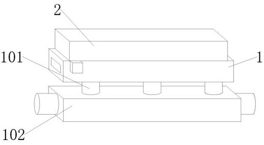
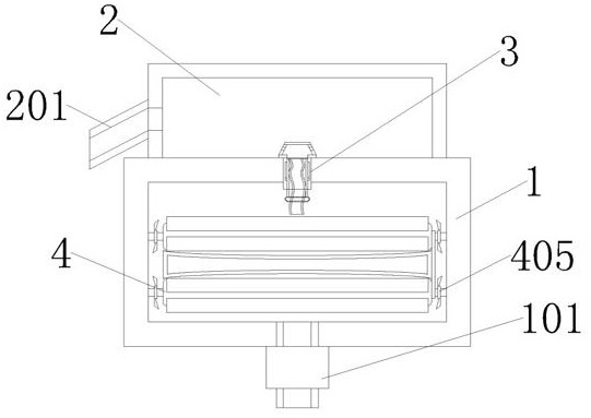
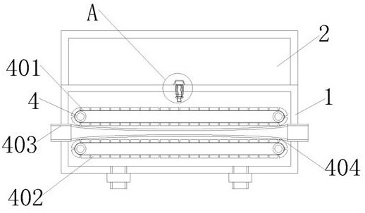
[0035] Embodiment 1: A non-hydraulic plate quenching device and method for continuous quenching of steel strips, including an outer box 1 and a drainage box 2, the top of the outer box 1 is fixedly connected with the drainage box 2, and the top of the outer box 1 is fixedly connected with a The water guide assembly 3 for discharging the cold liquid is rotatably connected to the inside of the outer box 1 with a rotatable assembly 4 capable of rotating water flow for heat exchange.

[0036] The inside of the water guide assembly 3 is movably connected with an inner pipe 301, the two sides of the inner pipe 301 are fixedly connected with sliders 302, the bottom of the inner pipe 301 is fixedly connected with a floating pipe 304, and the top of the inner pipe 301 is fixedly connected with a drain cover 303, The inside of the inner tube 301 is fixedly connected with a limiting ring 307 , the top of the limiting ring 307 is movably connected with a cover piece 305 , and the bottom of...

Embodiment 2

[0043] Embodiment 2: The difference between Embodiment 2 and Embodiment 1 is that the rotating assembly 4 is driven by a motor connected to the outer surface of the outer box 1;

[0044] The outer surfaces of the two rotating assemblies 4 are movably connected with crawler belts 401 , the outer surfaces of the crawler belts 401 are fixedly connected with heat conduction fins 402 , and the two rotating assemblies 4 are movably connected with heat conduction plates 404 , and both sides of the heat conduction plate 404 are fixedly connected with extending To the feeding pipe 403 on both sides of the outer box 1 , the outer surface of the rotating assembly 4 is fixedly connected with a fixed pipe 405 , and the outer surface of the fixed pipe 405 is fixedly connected with a water guide piece 406 .

[0045] The track 401 is made of zinc alloy, the heat conducting sheet 402 is made of copper, and the heat conducting plate 404 is made of graphite cold iron.

[0046] There are multiple...

Embodiment 3

[0050] Embodiment 3: The difference between embodiment 3 and embodiment 2 is that a water pump 101 is fixedly connected to the bottom of the outer box 1, and the water outlet end of the water pump 101 extends to the inner bottom of the outer box 1, and the water inlet end of the water pump 101 is fixedly connected with a cooling The liquid tank 102 and the back of the drainage tank 2 are fixedly connected with an outlet pipe 201 .

[0051] Wherein, three water pumps 101 are provided, and the three water pumps 101 are equidistantly distributed on the bottom of the outer box 1 .

[0052] Wherein, one end of the water outlet pipe 201 is inclined downward.


PUM


Abstract

The invention provides a hydraulic-plate-free quenching device and method for continuous quenching of a steel strip. The hydraulic-plate-free quenching device comprises an outer box and a drainage box. The top of the outer box is fixedly connected with the drainage box, the top of the interior of the outer box is fixedly connected with a water guide assembly which can discharge cold liquid, and the interior of the outer box is rotationally connected with a rotating assembly which can rotate water flow to conduct heat exchange. According to the hydraulic-plate-free quenching device and method, the cold liquid flows in the outer box and makes contact with a high-temperature iron sheet, the temperature of the cold liquid can be increased, after the temperature of the cold liquid is increased, the liquid level can be increased through thermal expansion and cold contraction in the device, the liquid can rise to the drainage box, the liquid is rapidly discharged through the water guide assembly, a water guide device of the water guide assembly discharges the liquid in time, flowing of the liquid is accelerated, and the heat can be timely dissipated; and water flow in the outer box can be rapidly exchanged through the rotating assembly, the temperature of the surface of the steel strip can be rapidly circulated, the temperature of the surface of the steel strip can be uniformly exchanged, the heat exchange area of the steel strip and the flowing area of water are increased, and the quenched part of the steel strip can be uniform.

Description

technical field [0001] The invention relates to the field of continuous quenching of steel strips, in particular to a non-hydraulic plate quenching device and method for continuous quenching of steel strips. Background technique [0002] The continuous quenching of the steel strip is to quench the surface of the steel strip. It is to spray water to cool the surface of the steel strip immediately after the temperature rises, so that the surface of the steel strip can obtain a hardened layer of a certain depth, which can make the surface of the steel strip wear-resistant and torsion-resistant. , Anti-bending fatigue and contact fatigue effects, and when the steel strip is quenched, it is impacted by liquid, and the liquid flow affects the quenching environment, causing a certain impact on the steel strip. [0003] In view of the above-mentioned technical problems in the preparation device for water-in-water coating production, it was found through retrieval that there is a pat...

Claims


Application Information

Patent Timeline
Patent Type & Authority Applications(China)
IPC IPC(8): C21D1/673C21D9/573
CPCC21D1/673C21D9/573C21D9/0062
Inventor 陈爱东施启斌陈叶宇东
Owner 南通江勤美金属制品有限公司
Learn More