Thermal runaway vacuum cooling device for lithium ion battery in transformation environment

A lithium-ion battery, vacuum cooling technology, applied in measuring devices, secondary batteries, measuring electrical variables, etc., can solve the problems of slow cooling rate, low efficiency, low efficiency of fire extinguishing and cooling, etc.

Pending Publication Date: 2021-12-10
CIVIL AVIATION FLIGHT UNIV OF CHINA
View PDF0 Cites 3 Cited by
  • Summary
  • Abstract
  • Description
  • Claims
  • Application Information

AI Technical Summary

Problems solved by technology

[0006] When the thermal runaway of the lithium-ion battery occurs, the traditional fire extinguishing system is carried out under normal pressure, the fire extinguishing cooling rate is slow, and the efficiency is low. When the aircraft is flying at high altitude, the aircraft will be in a variable pressure and low temperature environment for a long time When using an aircraft to transport lithium-ion batteries or use lithium-ion batteries in an aircraft, the lithium-ion batteries will also be in a state of variable voltage. When the lithium-ion batteries are thermally out of control, it will cause high temperature, smoke, etc. in a short period of time. Fire or even explosion, so it is particularly necessary to study the thermal runaway behavior of lithium-ion batteries in a variable pressure environment, and the rapid cooling after thermal runaway occurs
[0007] However, nowadays, domestic and foreign studies on thermal runaway and thermal safety of lithium-ion batteries are usually carried out in normal temperature and pressure environments, and it is impossible to study the thermal runaway behavior of lithium-ion batteries in a variable pressure environment.
And the cooling efficiency of lithium-ion battery thermal runaway is low, such as manual use of dry powder fire extinguishers and carbon dioxide fire extinguishers, etc., lack of efficient cooling system, and the cooling method of lithium-ion battery thermal runaway is not mature enough

Method used


Image

  • Thermal runaway vacuum cooling device for lithium ion battery in transformation environment
  • Thermal runaway vacuum cooling device for lithium ion battery in transformation environment
  • Thermal runaway vacuum cooling device for lithium ion battery in transformation environment

Examples


Embodiment Construction

[0027] The following will clearly and completely describe the technical solutions in the embodiments of the present invention with reference to the accompanying drawings in the embodiments of the present invention. Obviously, the described embodiments are only some, not all, embodiments of the present invention. Based on the embodiments of the present invention, all other embodiments obtained by persons of ordinary skill in the art without making creative efforts belong to the protection scope of the present invention.

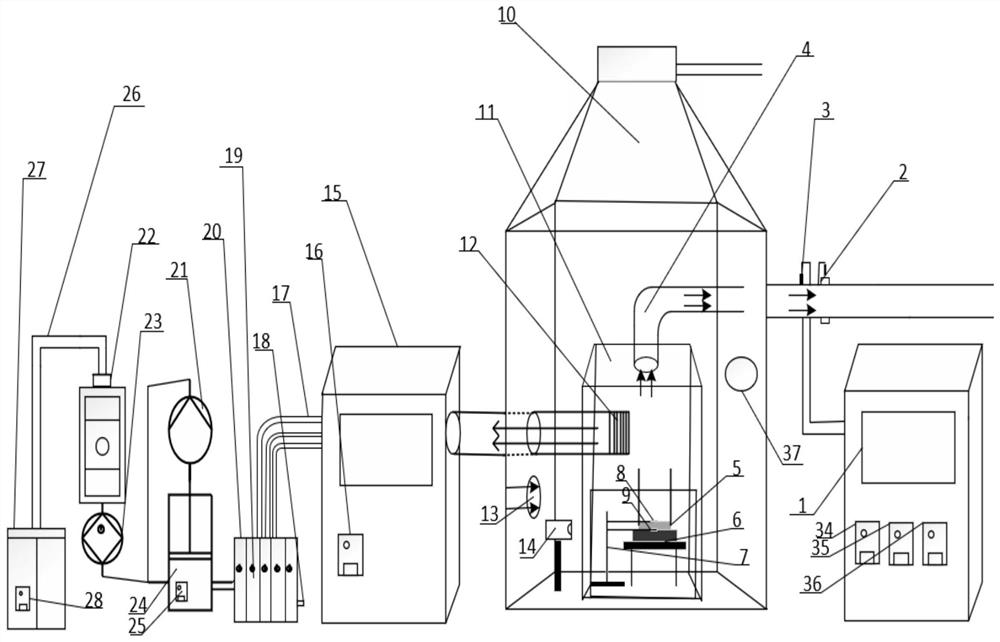
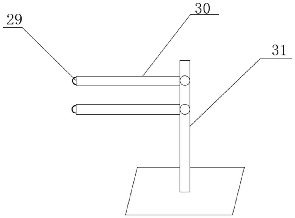
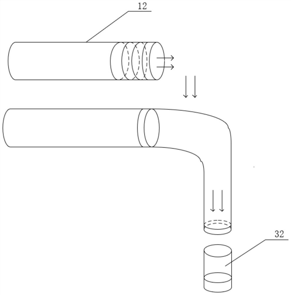
[0028] see Figure 1-4, the present invention provides a technical solution: a vacuum cooling device for thermal runaway in a lithium-ion battery variable voltage environment, such as figure 1 As shown, the device includes an integrated control and analysis system 1 for the experimental cabin, a dynamic temperature and pressure change experimental cabin 10, a vacuum cooling system, and an internal experimental cabin 11 arranged inside the dynamic temperature a...


PUM


Abstract

The invention discloses a thermal runaway vacuum cooling device for a lithium ion battery in a voltage transformation environment. The thermal runaway vacuum cooling device comprises an experiment cabin control and analysis integrated system, a dynamic temperature voltage transformation experiment cabin, a vacuum cooling system and an experiment internal cabin arranged in the dynamic temperature voltage transformation experiment cabin. According to the device, thermal runaway experiment research of multiple lithium ion batteries can be realized, and large-scale rapid cooling of the multiple batteries can be carried out after thermal runaway; lithium ion battery thermal runaway research under different working conditions (low voltage, low temperature and the like) can be realized; the surface temperature of the lithium ion battery can be measured in real time, the temperature change of the lithium ion battery under different working conditions during thermal runaway of the battery is studied, and meanwhile, the cooling relation of thermal runaway of different battery numbers can be studied; and a more valuable research method is provided for thermal runaway behavior analysis of thermal runaway of the lithium ion battery in a low-voltage environment and accurate and rapid cooling after thermal runaway.

Description

technical field [0001] The invention relates to the technical field of thermal runaway cooling of lithium ion batteries, in particular to a vacuum cooling device for thermal runaway of lithium ion batteries in a variable voltage environment. Background technique [0002] In 1970, M.S.Whittingham of Exxon used titanium sulfide as the positive electrode material and metal lithium as the negative electrode material to make the first lithium battery, and the development of lithium batteries began. Lithium-ion batteries have been invented and used since the 1990s. The history of lithium-ion batteries has been around for a while. Lithium-ion batteries have advantages such as high specific energy, high voltage, and long cycle life, and are currently widely used. It is involved in mobile phones, laptop computers, electric vehicles and other fields, especially in the fields of civil aviation and aerospace. The future development fields are broad, such as aircraft avionics systems, ae...

Claims


Application Information

Patent Timeline
IPC IPC(8): G01R31/385G01R31/389G01R31/396G01R1/02H01M10/613H01M10/6568
CPCG01R31/385G01R31/389G01R31/396G01R1/02H01M10/613H01M10/6568Y02E60/10
Inventor 陈现涛刘杭鑫赵晨曦张旭孙强贾井运
Owner CIVIL AVIATION FLIGHT UNIV OF CHINA
Why Eureka
Try Eureka