
Swing type high-power X-ray conversion target device

A target conversion, high-power technology, applied in the direction of X-ray tube, X-ray tube electrodes, X-ray tube parts, etc., to achieve uniform flow rate, increase contact area, and prolong service life.

Pending Publication Date: 2021-12-10
CGN DASHENG ELECTRON ACCELERATOR TECH
View PDF0 Cites 1 Cited by
  • Summary
  • Abstract
  • Description
  • Claims
  • Application Information

AI Technical Summary

Problems solved by technology

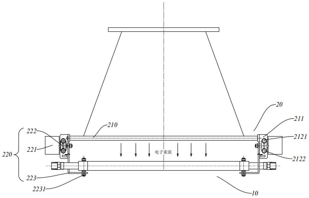
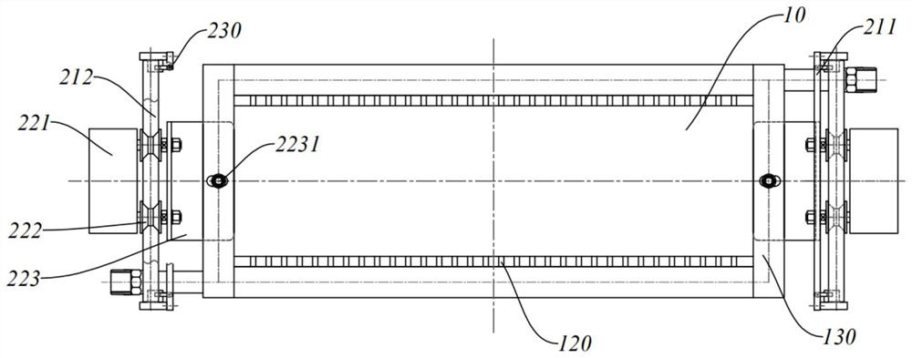
[0005] Aiming at the above-mentioned problems existing in the prior art, the present invention provides a swinging high-power X-ray conversion target device. The support assembly of the conversion target can drive the conversion target to reciprocate linear motion and reciprocating swinging motion, so that the electron beam will not fall on the target. Bombarding at the same position for a long time avoids target deformation or premature damage caused by local overheating of the conversion target, and effectively improves the uniformity of X-ray output; in addition, the conversion target is realized by combining heavy and light metal composite plates and coolant pipes The generation of X-rays and the filtration of low-energy rays after bombardment by high-energy electron beams not only have high conversion efficiency, but also can avoid direct contact between the coolant and the heavy metal plate while ensuring a good cooling effect, without target corrosion hidden dangers and sealing Ring replacement problem, simple structure, high reliability, long service life

Method used


Image

  • Swing type high-power X-ray conversion target device
  • Swing type high-power X-ray conversion target device
  • Swing type high-power X-ray conversion target device

Examples


Embodiment Construction

[0029] The present invention will be described in detail below with reference to the accompanying drawings and specific embodiments.

[0030] like figure 1 As shown, a swing type high-power X-ray conversion target device includes a conversion target 10 and a support assembly 20 for supporting the conversion target 10, and the conversion target 10 and the support assembly 20 are arranged below the scanning window.

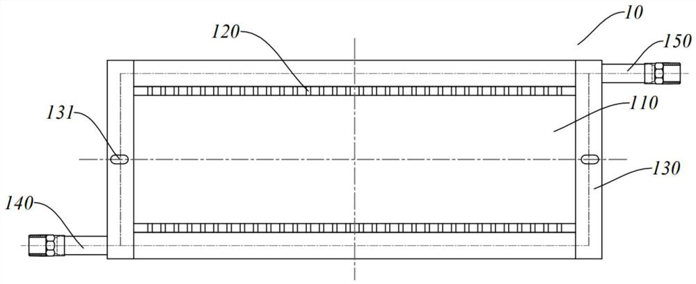
[0031] like image 3 , Figure 4 , Figure 5 As shown, the conversion target 10 includes a metal clad plate 110, a plurality of cooling liquid pipes 120 disposed under the metal clad plate 110, side fixing frames 130 disposed on both sides of the short sides of the metal clad plate 110, and each of which is disposed on the metal clad plate 110. The cooling liquid input pipe 140 and the cooling liquid output pipe 150 on both sides of the long side of 110 , and the cooling liquid pipe 120 is arranged between the cooling liquid input pipe 140 and the cooling liquid ...


PUM


Abstract

The invention relates to a swing type high-power X-ray conversion target device which comprises a conversion target and a supporting assembly used for supporting the conversion target, the conversion target and the supporting assembly are arranged below a scanning window, the supporting assembly comprises a supporting frame and a motor driving mechanism, and the supporting frame comprises a frame body and guide rails arranged on the two sides of the frame body; motor driving mechanisms are arranged on the guide rails on the two sides, each motor driving mechanism comprises a driving motor, a pulley and a connecting plate, the pulleys are arranged on the guide rails, the driving motors drive the pulleys to move and drive the connecting plates to move along with the pulleys, and the connecting plates are hinged to the conversion target. The supporting assembly drives the conversion target to do reciprocating rectilinear motion and reciprocating swing motion, long-time bombardment of electron beams at the same position of the target is avoided, the service life of the target is prolonged, and the uniformity of X-ray output is improved, and a cooling liquid pipe is arranged at the lower end of a metal composite plate of the conversion target. And a good cooling effect is guaranteed, meanwhile, direct contact between the cooling liquid and the heavy metal plate is avoided, and target corrosion hidden danger and sealing ring replacement problems are avoided.

Description

technical field [0001] The invention belongs to the technical field of irradiation processing, and particularly relates to a swing type high-power X-ray conversion target device. Background technique [0002] In the field of irradiation processing technology, in order to make up for the limitations in the practical application of irradiation processing caused by weak electron beam penetration, low utilization rate of γ-rays and fixed attenuation, high-energy and high-power electron beams are used to bombard heavy metal targets. The obtained X-ray source has both the advantages of the above two kinds of rays. In recent years, the development of domestic γ-irradiation sources has been limited due to insufficient market supply of cobalt-60 sources, decommissioning of sources, and environmental problems of γ-irradiation devices. It can be expected that the use of high-energy electron beams or the use of high-energy electron beams to target X-rays to replace cobalt sources will ...

Claims


Application Information

Patent Timeline
Patent Type & Authority Applications(China)
IPC IPC(8): H01J35/10
CPCH01J35/101H01J35/106
Inventor 陆洁平倪晓敏査军肖珺陈海
Owner CGN DASHENG ELECTRON ACCELERATOR TECH
Learn More