
Machining method of air heater injector

The technology of an air heater and a processing method, which is applied in the field of air heaters, can solve the problems of uneven fuel atomization, easy burning and melting equipment gas, high processing cost, etc., so as to reduce the technical difficulty of processing, swirl and atomization effects. Good, stable injection flow

Active Publication Date: 2021-12-14
XIAN YUANHANG VACUUM BRAZING TECH
View PDF11 Cites 0 Cited by
  • Summary
  • Abstract
  • Description
  • Claims
  • Application Information

AI Technical Summary

Problems solved by technology

If the injection flow rate is within the design range, the swirling effect of the injector is good, the fuel atomization is uniform and high, the vibration of the flame stabilization equipment is small, and the impact on the service life of the injector is small. When the injection flow rate exceeds the design range or the injection The swirling effect of the tangential hole of the device is poor, resulting in uneven fuel atomization, rapid decline in the combustion efficiency of the air heater and local high temperature due to excessive fuel, not only easy to burn the equipment but also cause gas turbulence, that is, damage to the heating equipment is also serious Affects the performance of the air heater
At present, when using the existing technology to process the air heater injector, when processing the square hole, it is perforated by the forming electrode. The processing cost of the square hole is processed by this processing method, and the processing efficiency is low, so it is not suitable for mass production.
When brazing the liquid nozzle, the solder is easy to block the flow hole of the liquid nozzle, which affects the flow requirement of the flow hole, resulting in poor quality of processed products and unnecessary losses.

Method used


Image

  • Machining method of air heater injector
  • Machining method of air heater injector
  • Machining method of air heater injector

Examples


Embodiment

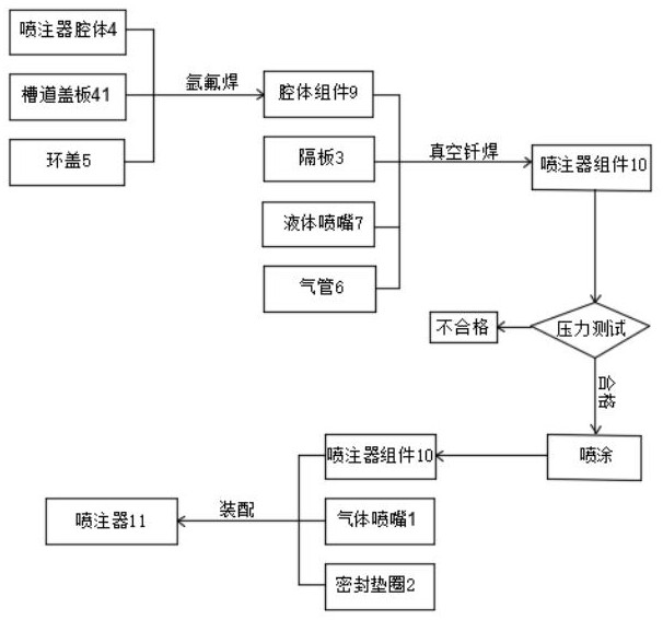
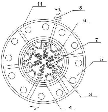
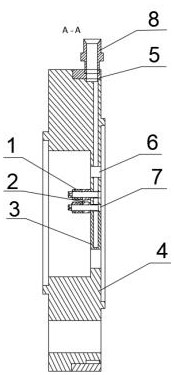
[0051] use as image 3In the method shown, a square groove is milled on the injector cavity 4 by milling, and then the channel cover plate 41 is welded to the square groove by argon arc welding to form a square hole.

[0052] use as Figure 4 In the method shown, the sinking platform 42 is washed and processed on the partition plate 3 by washing and processing. The size of the sinking platform is 14mm in diameter and 1mm in height. The sinking platform 42 can keep the liquid flow hole away from the brazing seam, and is used to avoid During welding, the solder blocks the liquid flow hole.

[0053] The liquid nozzle 7 and the gas pipe 6 need to pass through the holes of the injector cavity 4 and the partition plate 3 at the same time and cooperate on the machining center to reach the position of the hole between the injector cavity 4 and the partition plate 3 Similarly, it can reduce the difficulty of assembly and improve the quality of brazing seam.

[0054] The ring cover 5...


PUM

PropertyMeasurementUnit
diameteraaaaaaaaaa
heightaaaaaaaaaa

Abstract

The invention relates to a machining method of an air heater injector. The method comprises the following steps that S1, a channel cover plate and an annular cover are welded to an injector cavity in an argon arc welding mode to form a cavity assembly; S2, the cavity assembly, a partition plate, a liquid nozzle and an air pipe are installed and welded into an injector assembly through vacuum brazing; S3, the installed and welded injector assembly is subjected to a pressure test, and the step S4 is executed on the qualified injector assembly; S4, paint is sprayed to the injector assembly qualified in the pressure test; and S5, a gas nozzle and a sealing gasket are assembled on the injector assembly sprayed with the paint, and the qualified injector is formed. By adopting the machining method, the machining difficulty and the machining cost are reduced, the quality of the machined product is good, and the machining efficiency is effectively improved.

Description

technical field [0001] The invention belongs to the technical field of air heaters, and in particular relates to a processing method of an air heater injector. Background technique [0002] As an important part of the air heater, the injector is connected to the combustion chamber of the air heater. The change of its injection flow rate and the swirling effect of the tangential hole of the fuel liquid nozzle can directly affect the ignition stability and combustion efficiency of the heater. And the change law of the total outlet temperature uniformity. If the injection flow rate is within the design range, the swirling effect of the injector is good, the fuel atomization is uniform and high, the vibration of the flame stabilization equipment is small, and the impact on the service life of the injector is small. When the injection flow rate exceeds the design range or the injection The swirling effect of the tangential hole of the device is poor, resulting in uneven fuel ato...

Claims


Application Information

Patent Timeline
Patent Type & Authority Applications(China)
IPC IPC(8): B23P15/00
CPCB23P15/00
Inventor 王程成任军康路路兰新杰周伟超李文昌
Owner XIAN YUANHANG VACUUM BRAZING TECH
Learn More