Eureka AIR delivers breakthrough ideas for toughest innovation challenges, trusted by R&D personnel around the world.

Multi-stage centrifugal compression system and optimization method thereof

A technology of centrifugal compression and system optimization, which is applied in separation methods, chemical instruments and methods, and separation of dispersed particles. It can solve the problems of fluctuations in system gas production and operating conditions, large pressure loss of interstage coolers, and reduced system reliability. problems, to achieve reliable and stable system operation, stable gas production, and stable intake conditions

Inactive Publication Date: 2021-12-14
湖南雅立科技开发有限公司
View PDF0 Cites 0 Cited by
  • Summary
  • Abstract
  • Description
  • Claims
  • Application Information

AI Technical Summary

Problems solved by technology

[0003] The above process mainly has the following problems. Air is directly sucked in from the environment. When the ambient air temperature is high, the energy consumption of the first-stage compression is high, and the gas production volume becomes smaller; the gas production volume and operating conditions of the system fluctuate with the ambient temperature.
The second is that the pressure loss of the interstage cooler is relatively large, making the actual pressure ratio of the system greater than the required pressure ratio, resulting in increased energy consumption of the system, and may also increase the number of compression stages; at the same time, the interstage cooler makes the system complex and the system reliability Reduced maintenance workload
The third is that the adsorption dryer needs to use electric energy to drive regeneration, which consumes a large amount of electric energy needlessly. At the same time, a large amount of heat generated by the compressor is discharged to the atmosphere by the cooling tower of the cooler.

Method used

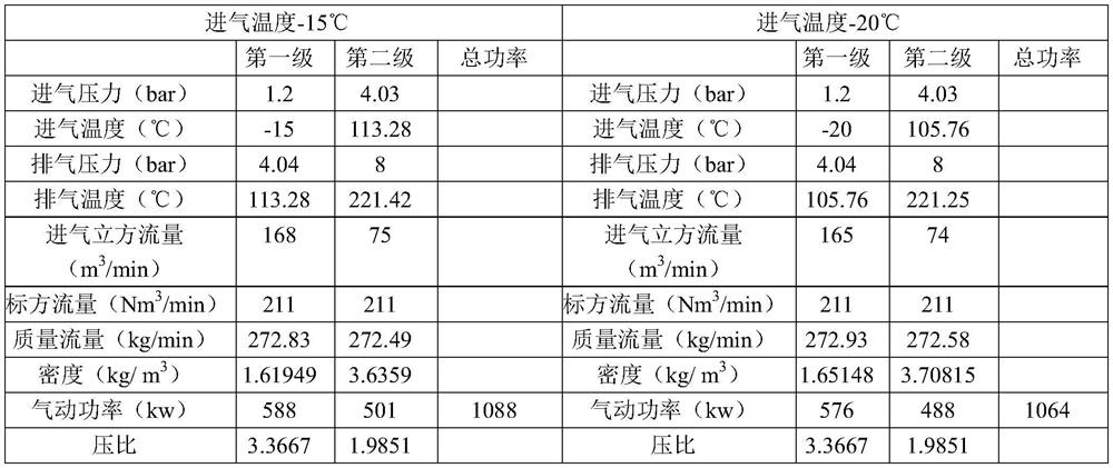
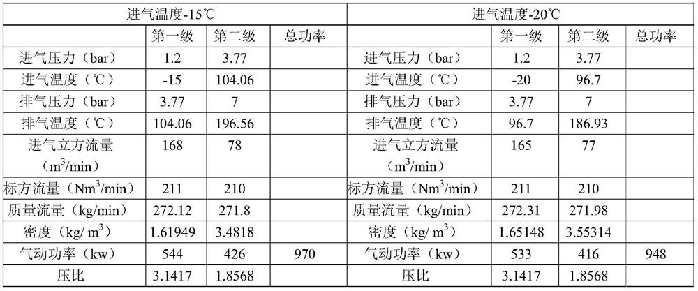

Image

  • Multi-stage centrifugal compression system and optimization method thereof
  • Multi-stage centrifugal compression system and optimization method thereof
  • Multi-stage centrifugal compression system and optimization method thereof

Examples


Embodiment Construction

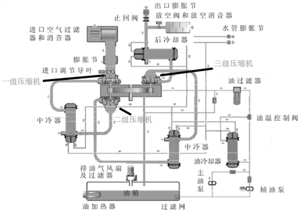
[0034] figure 1 It shows a typical three-stage centrifugal compression system commonly used at present. It can be seen from the figure that the multi-stage compressor is driven by a motor, and the system is complicated. device, etc.) to the cooling box connection, such as figure 2 As shown, this leads to further complexity of the system, and at the same time, the pressure loss between multiple stages is large, resulting in the actual pressure ratio of the system being smaller than the theoretical pressure ratio. For example: a three-stage compression system, the pressure ratios of the compressors are 2.5, 1.8, 1.8, the theoretical pressure ratio is 8.1, the actual measured final exhaust pressure is only 6.6kg, and the intake pressure is atmospheric pressure, that is, the resulting pressure ratio is only 6.6, and the interstage pressure loss leads to a significant pressure ratio loss.

[0035] The present invention cools the intake air of the centrifugal compression system, t...


PUM


Abstract

The invention discloses a multi-stage centrifugal compression system and an optimization method thereof. According to the invention, inlet air of the multi-stage centrifugal compression system is cooled and / or subjected to pressurizing treatment at the same time, at least one stage of intermediate cooling device in the multi-stage centrifugal compression system is removed, and two stages of centrifugal compressors without the intermediate cooling device are directly connected through a connecting pipe, so that the pressure ratio loss of the multi-stage centrifugal compressor system is reduced. The pressurizing treatment is realized through a fan, the air inlet pressure of the centrifugal compression system is increased, at least the air inlet pressure of the centrifugal compression system is guaranteed to be not lower than the ambient atmospheric pressure, the air inlet pressure of the centrifugal compression system is increased through pressurizing, and therefore the centrifugal compression system can operate normally when a cooling treatment system fails. Meanwhile, the reduction of the pressure ratio loss and the increase of the air inlet pressure can reduce the working pressure ratio of the centrifugal compressors and greatly reduce the energy consumption of the system under the condition of keeping the output pressure of the centrifugal compression system unchanged.

Description

technical field [0001] The present invention relates to a method for optimizing a multistage centrifugal compression system, in particular to a method for optimizing a centrifugal compression system by utilizing intake air treatment and a related multistage centrifugal compression system. Background technique [0002] Centrifugal compression systems are widely used in important fields of the national economy, including electronic semiconductor industry, steel, chemical industry, and air separation gas manufacturing industries. They are important industrial equipment and are also large energy consumers. Centrifugal compression systems are generally large-scale compression systems with large gas production. Due to the small unipolar pressure ratio of centrifugal compression, generally less than 3, multi-stage compression is often used in centrifugal compression systems. The typical process of existing air compression is: one-stage centrifugal The compressor sucks in the ambien...

Claims


Application Information

Patent Timeline
Patent Type & Authority Applications(China)
IPC IPC(8): F04D17/12F04D29/58F04D29/00B01D53/26
CPCF04D17/12F04D29/582F04D29/002B01D53/261
Inventor 袁一军黄宗华
Owner 湖南雅立科技开发有限公司
Why Eureka
Eureka Blog
Learn More