Heat-sensitive sensor and temperature measuring method

A thermal sensor and sensor technology, applied in the sensor field, can solve problems such as thermal sensor damage, user error message prompts, safety hazards, etc., and achieve the effect of increasing the scope of use, prolonging the service life, and improving the use experience.

Pending Publication Date: 2021-12-14
王林成
View PDF1 Cites 4 Cited by
  • Summary
  • Abstract
  • Description
  • Claims
  • Application Information

AI Technical Summary

Problems solved by technology

[0002] As a new type of clean and renewable secondary energy, lithium-ion batteries are affected by Joule heat, reaction heat, and polarization heat during the discharge process, and a large amount of heat will accumulate, which will increase the battery temperature and affect battery life and cycle. If the efficiency is serious, it will cause an explosion; if there is a short circuit or overshoot inside it, it may also cause an explosion due to high temperature; therefore, it is necessary to effectively monitor the heating of the lithium battery to eliminate potential safety hazards; at present, the most A direct and effective temperature detection method is to install a thermal sensor on the outer wall of the lithium battery, convert the thermal sensor into a standard electrical signal and send it to an external temperature detection instrument, and the temperature detection instrument will display the specific temperature value; currently, thermal sensors are used in lithium batteries. The general fixing methods for installing the battery box are: such as screw fixing, glue fixing and welding. First, screw fixing and glue fixing, the installation efficiency is slow during the installation process; if the screw is installed, if the operation is improper, it will damage the thermal sensor. It can cause physical damage; while fixing with glue, it is difficult to control the amount of colloid used and the fixed position, and the colloid has a long curing time and is easy to fall off; as for the use of welding, the high temperature generated by soldering and molten tin may damage the heat. Sensitive sensor, if this damage is not found, it will lead to errors in the temperature monitoring data of the lithium battery, and bring wrong information to the user, posing a serious safety hazard
[0003] For example, a Chinese patent with the application number CN201920321919.9 discloses a thermal sensor. The technical solution includes a first housing with arc-shaped surfaces on both sides. The upper end of the first housing is a plane. A thermal sensor is fixedly connected to the upper end of the first housing. An arc-shaped groove is also provided in the first housing. A guard plate parallel to the inner wall of the arc-shaped groove is provided in the arc-shaped groove. The number of the guard plates is two and symmetrical. Setting, the protective plate is also fixedly connected with some first springs, the other end of the first spring is vertically connected with the inner wall of the arc groove, the thermal sensor is also provided with a telescopic rod, and the telescopic rod is sleeved with a second spring; The technical solution uses the first spring and the guard plate, which can provide stronger clamping force and ensure that the thermal sensor can be stably and firmly fixed on the lithium battery. In addition, the heat conducting rod is made of metal material, and directly contacts the outer wall of the lithium battery. Compared with plastic materials, the thermal conductivity is larger, the temperature of the outer wall of the battery and the temperature actually measured by the sensor have a smaller error, the temperature sensing speed is faster, and the measurement is more accurate; but there are certain shortcomings in this technical solution. battery, and there is no lithium battery suitable for different thicknesses, which has caused the limitation of this technical solution

Method used


Image

  • Heat-sensitive sensor and temperature measuring method
  • Heat-sensitive sensor and temperature measuring method
  • Heat-sensitive sensor and temperature measuring method

Examples


Embodiment approach

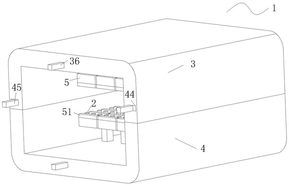
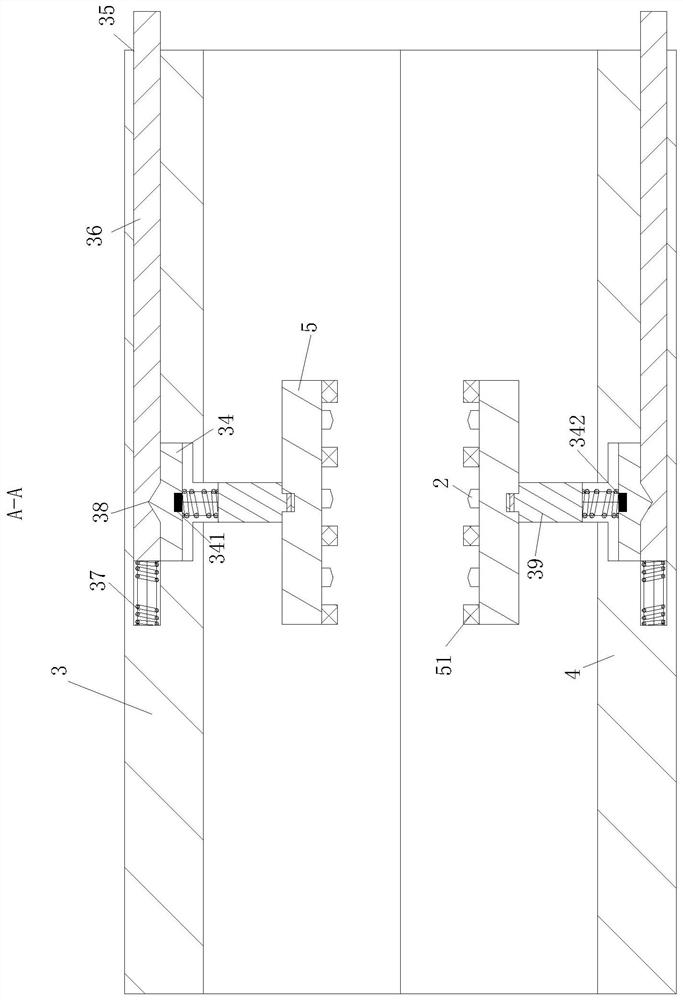
[0038] As an embodiment of the present invention, the surface of the clamping plate 5 is fixed with a flexible layer 51; the flexible layer 51 is spaced from the sensor 2, and the thickness of the flexible layer 51 is greater than the thickness of the sensor 2;

[0039] When working, the clamping plate 5 clamps the lithium battery, and the lithium battery first contacts with the flexible layer 51, and the flexible layer 51 is deformed under extrusion, and is closer to the shell of the lithium battery, increasing the friction so that the lithium battery cannot be dropped. At the same time, after the deformation of the flexible layer 51, the sensor 2 can be in contact with the lithium battery, so that the sensor 2 will not be squeezed by the lithium battery when it is clamped;

[0040] In the present invention, a flexible layer 51 is firmly connected to the surface of the clamping plate 5, and the flexible layer 51 and the sensor 2 are placed at intervals, and then the thickness ...


PUM


Abstract

The invention relates to the technical field of sensors, in particular to a heat-sensitive sensor and a temperature measuring method. The heat-sensitive sensor comprises shells, a sensor and a controller, wherein first grooves are uniformly formed in the corresponding inner end surfaces of a first shell and a second shell; a second groove communicates with a cavity; one end of a sliding rod is fixedly connected with the bottom of the second groove through a second spring; the end, away from the first shell, of a first spring is fixedly connected with a movable column; a clamping plate is hinged to the end, away from a fixing plate, of the movable column; and the surface of the clamping plate is fixedly connected with the sensor. According to the invention, limiting of the fixing plate is released by pressing the sliding rod, and then the fixing plate drives the first spring and the movable column to drive the clamping plate to clamp a lithium battery, so the purpose that the sensor is not damaged when the lithium battery is installed is achieved, temperature detection can be carried out on lithium batteries of different shapes, the application range of the heat-sensitive sensor is improved, and the service life of the heat-sensitive sensor is prolonged.

Description

technical field [0001] The invention relates to the technical field of sensors, in particular to a thermosensitive sensor and a temperature measuring method. Background technique [0002] As a new type of clean and renewable secondary energy, lithium-ion batteries are affected by Joule heat, reaction heat, and polarization heat during the discharge process, and a large amount of heat will accumulate, which will increase the battery temperature and affect battery life and cycle. If the efficiency is serious, it will cause an explosion; if there is a short circuit or overshoot inside it, it may also cause an explosion due to high temperature; therefore, it is necessary to effectively monitor the heating of the lithium battery to eliminate potential safety hazards; at present, the most A direct and effective temperature detection method is to install a thermal sensor on the outer wall of the lithium battery, convert the thermal sensor into a standard electrical signal and send ...

Claims


Application Information

Patent Timeline
Patent Type & Authority Applications(China)
IPC IPC(8): G01K1/143G01K1/08G01K1/12G01K13/00
CPCG01K1/143G01K1/08G01K1/12G01K13/00
Inventor 王林成徐浩波
Owner 王林成
Why Eureka
Try Eureka