Method for verifying range finding capability of laser range finder

A laser ranging machine and capability verification technology, applied in radio wave measurement systems, instruments, etc., can solve the problems of low verification efficiency, affect production efficiency, and difficult to verify, and achieve a wide coverage, convenient measurement, and improved production efficiency. Effect

Pending Publication Date: 2021-12-14
洛阳壹扬机电技术有限公司
View PDF0 Cites 2 Cited by
  • Summary
  • Abstract
  • Description
  • Claims
  • Application Information

AI Technical Summary

Problems solved by technology

The ranging ability of the laser rangefinder to directly verify the target is affected and limited by the aiming accuracy, site, weather, atmospheric visibility, etc. It is dif

Method used


Image

  • Method for verifying range finding capability of laser range finder
  • Method for verifying range finding capability of laser range finder
  • Method for verifying range finding capability of laser range finder

Examples


Embodiment 1

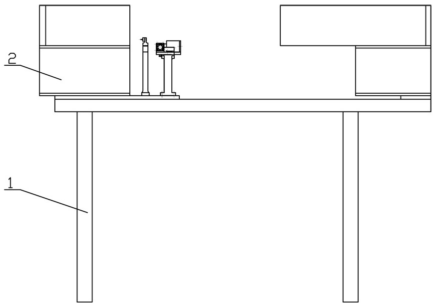
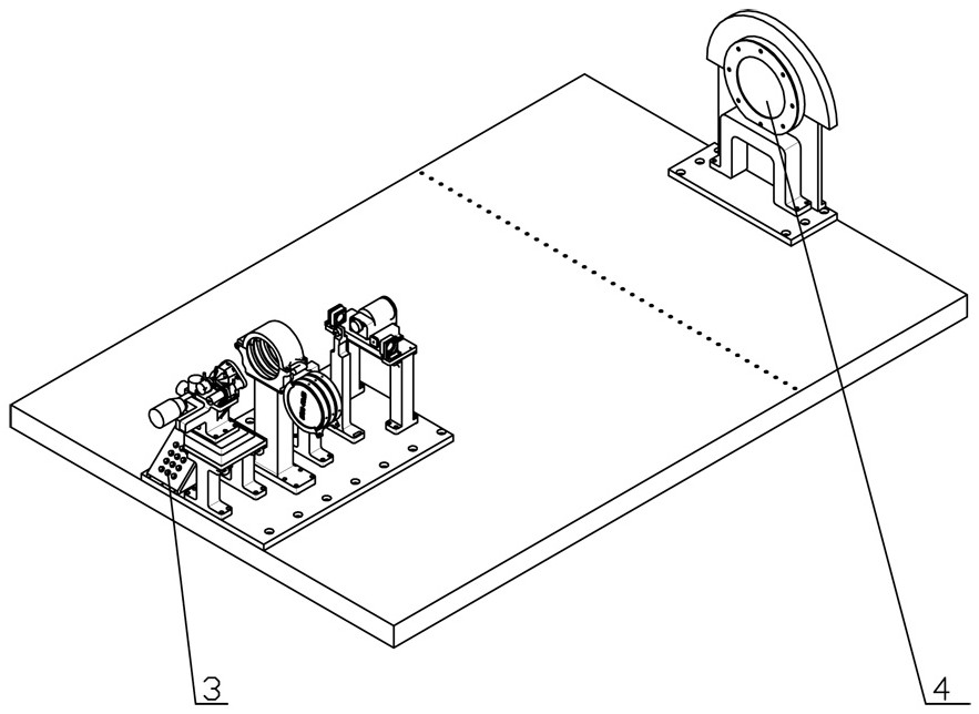
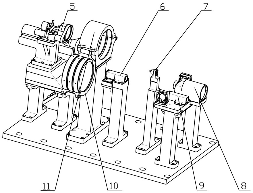
[0041] A method for verifying the range-finding ability of a laser range finder, the equipment using the method such as Figure 1-11 As shown, it includes a bracket 13 for installing the laser rangefinder 5, a reflection assembly 4 located at one side of the bracket 13, a focus assembly 7, a receiving system 8, a long-distance test emission system 6, and a short-distance test emission system 9 , Attenuation sheet bracket 11 and control panel 3.

[0042]The focus assembly 7 , the receiving system 8 , the long-distance test emission system 6 and the short-distance test emission system 9 are all located between the bracket 13 and the reflection assembly 4 . The reflection assembly 4 is installed on the workbench 1, and the support 13, the attenuation sheet support 11, the long-distance test transmitting system 6, the focus assembly 7 and the receiving system 8 are successively installed on the base plate, and the base plate is installed on the workbench 1, and the base plate and ...

Embodiment 2

[0064] The difference between this embodiment and Embodiment 1 is that, in this embodiment, an emission attenuation sheet is provided at the end of the emission housing away from the laser diode to adjust the energy of the laser pulse emitted by the remote test emission system.

Embodiment 3

[0066]The difference between this embodiment and Embodiment 1 is that when determining the installation position of the long-distance test emission system or the short-distance test emission system in this embodiment, the test card can be used to observe the position of the spot, thereby adjusting the long-distance test emission system or the short-distance test. The emitting system makes the emitted laser pulse just converge at the small aperture diaphragm after being reflected by the Newton mirror.


PUM


Abstract

The invention discloses a method for verifying the range finding capability of a laser range finder. The method comprises the following steps that: a first laser pulse is transmitted by a transmitting end in the laser range finder, and the first laser pulse is received by a receiving system after the first laser pulse is reflected multiple times; after receiving the first laser pulse signal, a receiving system controls a long-distance test transmitting system or a short-distance test transmitting system to transmit a laser pulse with a power being a set value after a set time delay, and the laser pulse is received by a receiving end in the laser range finder after being reflected multiple times; and the laser range finder can feed back a measured value, and the range finding capability of the laser range finder can be obtained according to the existence and size of the measured value. According to the invention, sites required by testing are greatly reduced, soverification of the distance measuring capability of the laser range finder can be carried out indoors and is not influenced by outdoor aiming precision, sites, weather, atmospheric visibility and the like, and production efficiency is further improved.

Description

technical field [0001] The invention relates to the technical field of rangefinder performance testing, in particular to a method for verifying the rangefinder capability of a laser rangefinder. Background technique [0002] The laser rangefinder has the advantages of small size, simple operation and high measurement accuracy, and it is widely used in various aspects such as military affairs, science and technology, production and construction. At present, when verifying the range measurement of the laser rangefinder, it is necessary to choose a suitable weather to establish a simulated target outdoors, and then measure the target. If the detected distance is consistent with the actual distance, the verification is qualified. The ranging ability of the laser rangefinder to directly verify the target is affected and limited by the aiming accuracy, site, weather, atmospheric visibility, etc. It is difficult to verify at any time, and the verification efficiency is low, which w...

Claims


Application Information

Patent Timeline
IPC IPC(8): G01S7/497
CPCG01S7/497
Inventor 董涛陈勇张凯祥
Owner 洛阳壹扬机电技术有限公司
Why Eureka
Try Eureka