Digital implementation method for sampling high-side IGBT temperature and bus voltage of motor controller
A technology of motor controller and bus voltage, applied in computer control, program control, general control system, etc., can solve the problems that the voltage and temperature cannot be obtained, and the consistency of the controller cannot be guaranteed, so as to achieve the improvement of control accuracy and monitoring Accuracy improvement and consistency, good consistency effect, good stability effect
- Summary
- Abstract
- Description
- Claims
- Application Information
AI Technical Summary
Problems solved by technology
Method used
Image
Examples
Embodiment 1
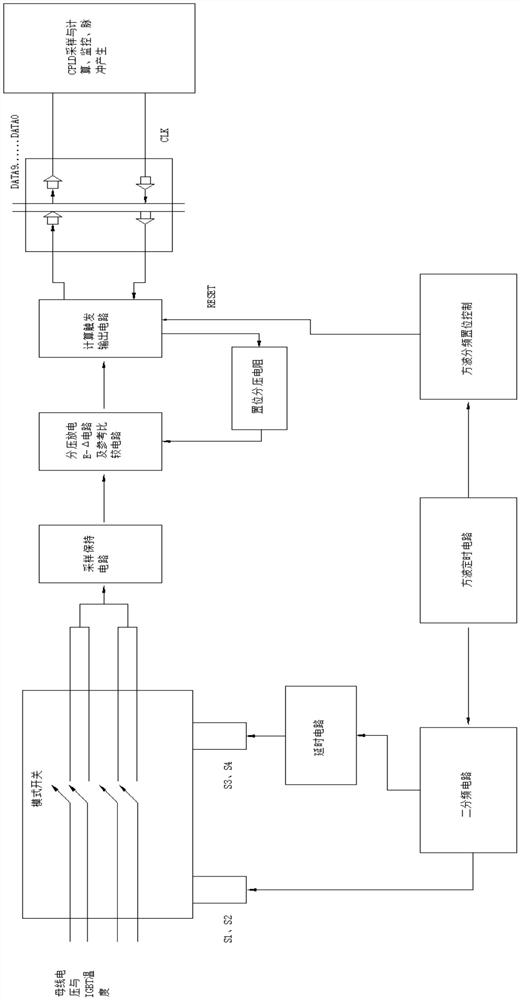
[0027] refer to Figure 1-2 , a digital implementation method for sampling the high-side IGBT temperature and the bus voltage of the motor controller, including the following steps:
[0028] S1: Ready mode switch, sample and hold circuit, voltage divider discharge E-Δ circuit and reference comparison circuit, calculation trigger output circuit, set voltage divider resistor, delay circuit, two frequency divider circuit, square wave timing circuit, square wave divider frequency setting control, and at the same time connect the mode switch to the sample-and-hold circuit, the sample-and-hold circuit is connected to the voltage-dividing discharge E-Δ circuit and the reference comparison circuit, and the voltage-dividing discharge E-Δ circuit and the reference comparison circuit are connected to the calculation trigger output circuit Connection, the calculation trigger output circuit is connected with the set voltage divider resistor, the set voltage divider resistor is connected wi...
Embodiment 2
[0040] refer to Figure 1-2 , a digital implementation method for sampling the high-side IGBT temperature and the bus voltage of the motor controller, including the following steps:
[0041] S1: Ready mode switch, sample and hold circuit, voltage divider discharge E-Δ circuit and reference comparison circuit, calculation trigger output circuit, set voltage divider resistor, delay circuit, two frequency divider circuit, square wave timing circuit, square wave divider frequency setting control, and at the same time connect the mode switch to the sample-and-hold circuit, the sample-and-hold circuit is connected to the voltage-dividing discharge E-Δ circuit and the reference comparison circuit, and the voltage-dividing discharge E-Δ circuit and the reference comparison circuit are connected to the calculation trigger output circuit Connection, the calculation trigger output circuit is connected with the set voltage divider resistor, the set voltage divider resistor is connected wi...
PUM
 Abstract
Description
Claims
Application Information
 - R&D
- Intellectual Property
- Life Sciences
- Materials
- Tech Scout
- Unparalleled Data Quality
- Higher Quality Content
- 60% Fewer Hallucinations
Browse by: Latest US Patents, China's latest patents, Technical Efficacy Thesaurus, Application Domain, Technology Topic, Popular Technical Reports.
© 2025 PatSnap. All rights reserved.Legal|Privacy policy|Modern Slavery Act Transparency Statement|Sitemap|About US| Contact US: help@patsnap.com


