Submersible pump rotor with high sealing performance

A submersible pump and sealing technology, which is applied to the components of the pumping device for elastic fluid, the pump, the pump device, etc. Protection, improve export efficiency, reduce the effect of sports wear

Pending Publication Date: 2021-12-17
XUZHOU MINGRUN MAGNETIC MATERIAL CO LTD
View PDF1 Cites 0 Cited by
  • Summary
  • Abstract
  • Description
  • Claims
  • Application Information

AI Technical Summary

Problems solved by technology

[0003] However, during the actual operation of the submersible pump, the negative pressure generating body is completely filled with the drawn water, and under the continuous rotation effect of the impeller, the drawn water is always maintained at an ultra-high pressure state. Through the assembly gap between the drive shaft of the rotor and the negative pressure generating body, the negative pressure generating body overflows, which leads to the short circuit of the driving parts in the motor and causes the "burn-in" problem. In addition, the existing double-end mechanical seals are arranged at both ends of the rotor. The sealing body with the same structure, the seals at both ends cause the rotor to run with high friction and wear, and the service life is short, and a large amount of heat is generated during motion friction and the heat of the electrode rotor cannot be dissipated quickly, resulting in serious heating of the motor, and there are certain defects
[0004] In view of this, the existing problems are studied and improved, and a submersible pump rotor with strong sealing is provided to solve the existing problems of high wear of sealing components and heat cannot be dissipated in time, aiming to use this technology to achieve The purpose of solving problems and improving practical value

Method used


Image

  • Submersible pump rotor with high sealing performance
  • Submersible pump rotor with high sealing performance
  • Submersible pump rotor with high sealing performance

Examples


Embodiment Construction

[0037] In order to make the object, technical solution and advantages of the present invention clearer, the present invention will be further described in detail below in combination with specific embodiments and with reference to the accompanying drawings. It should be noted that, in the case of no conflict, the embodiments of the present invention and the features in the embodiments can be combined with each other.

[0038] It is understood that these descriptions are exemplary only, and are not intended to limit the scope of the invention.

[0039] A submersible pump rotor with strong sealing performance provided by some embodiments of the present invention will be described below with reference to the accompanying drawings.

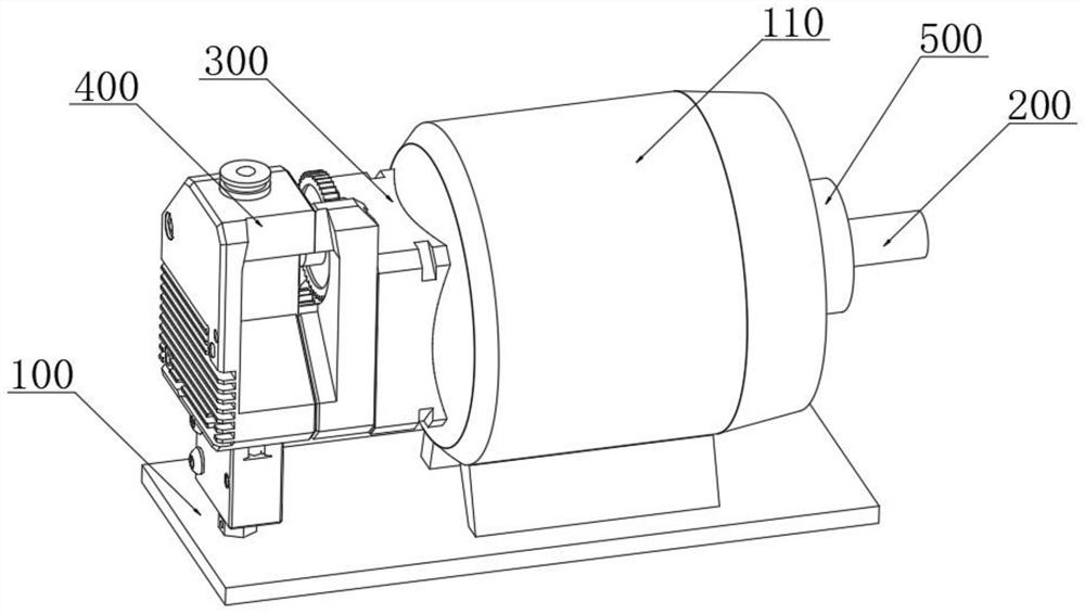
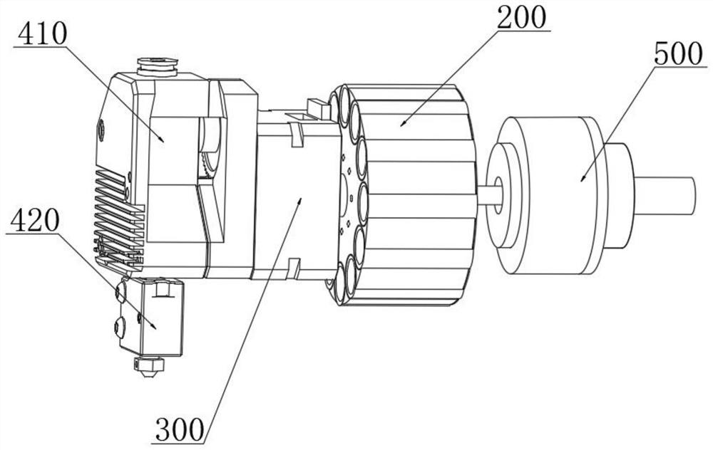
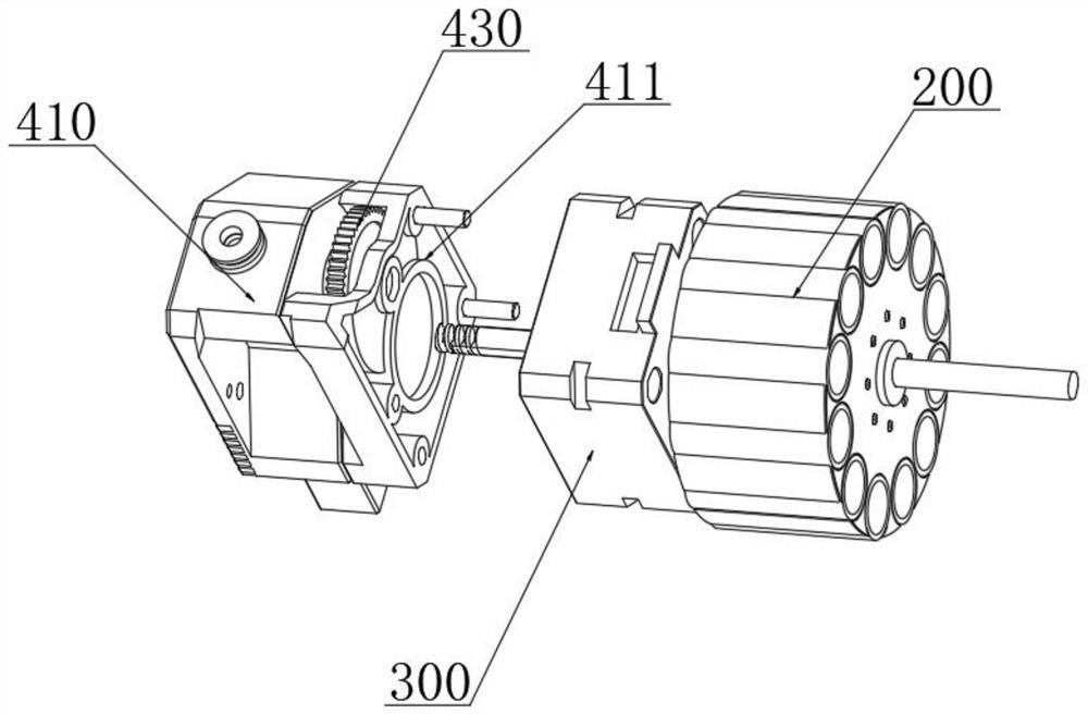
[0040] to combine Figure 1-8As shown, a submersible pump rotor with strong airtightness provided by the present invention includes: a water pump frame 100, a motor sleeve 110, a motor rotor 200, an electrode contact box 300 and an air curtain coolin...


PUM


Abstract

The invention discloses a submersible pump rotor with high sealing performance. The submersible pump rotor comprises a water pump rack, a motor sleeve seat, a motor rotor, an electrode contact box and an air curtain cooling assembly, wherein the electrode contact box and the air curtain cooling assembly are fixedly arranged at one end of the motor sleeve seat; the outer side of the motor rotor is rotationally sleeved with a dynamic sealing assembly and is fixed at one end of the motor sleeve seat; the motor rotor is movably sleeved with the motor sleeve seat; and one side of the electrode contact box is in sealed connection with the side surface of the air curtain cooling assembly. According to the submersible pump rotor, the air curtain cooling assembly and the dynamic sealing assembly are arranged at the two ends of the motor rotor respectively to carry out motion sealing of a rotor structure, the air curtain cooling assembly forms a saturated air pressure cavity in an air inlet end box through external pumping air to refuse the entering of water liquid to seal one end of the motor rotor, and the protection of the two ends of the motor rotor is guaranteed through the motion abutting sealing of the dynamic sealing assembly and the surface of the motor rotor, so that the effective sealing protection of the submersible pump rotor is realized, and the waterproof capacity is improved.

Description

technical field [0001] The invention relates to the technical field of water pump manufacturing, in particular to a submersible pump rotor with strong sealing performance. Background technique [0002] Submersible pump is an important equipment for deep well water extraction. When in use, the whole unit submerges into the water to extract groundwater to the surface. It is used for domestic water, mine emergency, industrial cooling, farmland irrigation, seawater lifting, ship load adjustment, and can also be used for fountain landscape. For example, the Chinese patent application CN200410041188.0 is a double-end mechanical seal for centrifugal pumps, which is characterized in that the double-end seal is pressed by a drum-shaped rubber ring, and the two ends of the drum-shaped rubber ring have radial anti-rotation and axially movable connectors and The pump body is connected, and the outer circumference of the drum-shaped rubber ring is sealed by a sealing box. The cavity form...

Claims


Application Information

Patent Timeline
Patent Type & Authority Applications(China)
IPC IPC(8): F04D13/08F04D29/58F04D29/08F04D29/02F04D29/06
CPCF04D13/086F04D13/083F04D13/0606F04D29/5806F04D29/5886F04D29/086F04D29/026F04D29/061
Inventor 刘干滨
Owner XUZHOU MINGRUN MAGNETIC MATERIAL CO LTD
Why Eureka
Try Eureka