Eureka AIR delivers breakthrough ideas for toughest innovation challenges, trusted by R&D personnel around the world.

Cleaning cycle evaluation method, device and equipment for condensing lens field of photo-thermal power station

A technology of photothermal power stations and concentrators, applied in the field of solar energy applications, can solve problems affecting the energy conversion efficiency of the concentrator field, the decline in the average annual power generation of the unit, and the increase in the cost of electricity per unit

Pending Publication Date: 2021-12-17
SHANGHAI POWER EQUIP RES INST
View PDF0 Cites 0 Cited by
  • Summary
  • Abstract
  • Description
  • Claims
  • Application Information

AI Technical Summary

Problems solved by technology

[0003] Concentrating mirror field is a key component of photothermal energy conversion in photothermal power plants. The mirror surface of the concentrating mirror field is easily affected by factors such as dust, wind and sand, and rain in the environment, which leads to a gradual decrease in the mirror reflectivity of the reflector, thereby affecting the energy of the concentrating mirror field. The conversion efficiency will eventually lead to the loss of power generation of the solar thermal power station under the same irradiation conditions, the annual average power generation of the unit will decrease, and the cost per unit of electricity will increase

Method used


Image

  • Cleaning cycle evaluation method, device and equipment for condensing lens field of photo-thermal power station
  • Cleaning cycle evaluation method, device and equipment for condensing lens field of photo-thermal power station
  • Cleaning cycle evaluation method, device and equipment for condensing lens field of photo-thermal power station

Examples


Embodiment 1

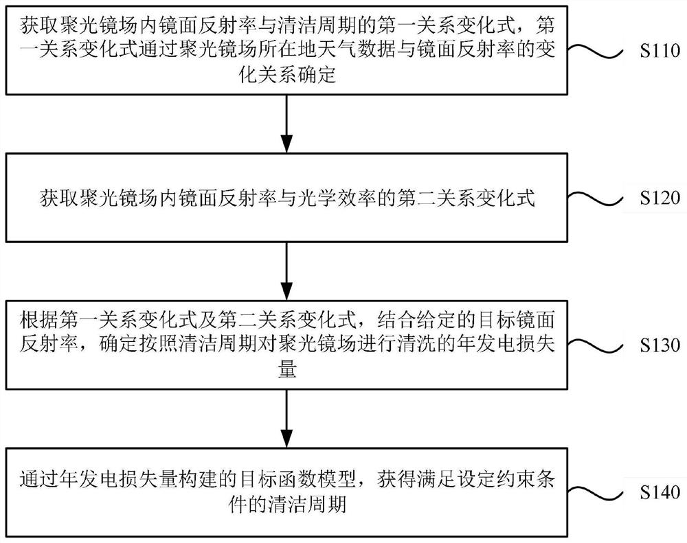
[0027] figure 1 It is a flow chart of a method for evaluating the cleaning cycle of the condenser field of a photothermal power station provided in Embodiment 1 of the present invention. This embodiment is applicable to the cleaning of the condenser field of a photothermal power station. To perform, the device may be implemented by software and / or hardware.

[0028] Such as figure 1 As shown, the method specifically includes the following steps:

[0029] S110. Acquire a first variation expression of the relationship between the mirror reflectance and the cleaning period in the condenser field, and the first relationship variation is determined by the change relationship between the weather data of the location of the condenser field and the mirror reflectivity.

[0030] Among them, the specular reflectance is a parameter of the ability of the specular reflection in the condenser field to reach the specular sunlight, and can be expressed by the ratio of the radiant flux refle...

Embodiment 2

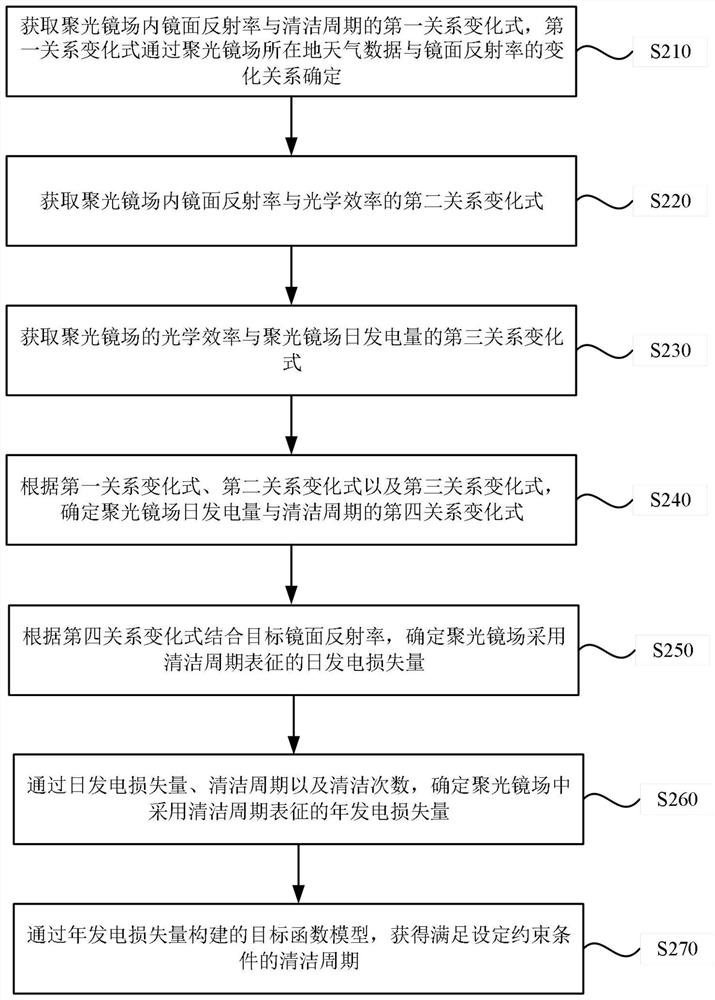
[0057] figure 2 It is a flow chart of a method for evaluating the cleaning cycle of the condenser field of a photothermal power plant provided by Embodiment 2 of the present invention. On the basis of the above-mentioned embodiments, this embodiment further optimizes the cleaning cycle evaluation method for the condenser mirror field of the above-mentioned photothermal power station.

[0058] Such as figure 2 As shown, the method specifically includes:

[0059] S210. Obtain a first variation expression of the relationship between the reflectance of the mirror surface and the cleaning cycle in the condenser field, and the variation expression of the first relationship is determined by the change relationship between the weather data of the location of the condenser field and the reflection ratio of the mirror surface.

[0060] S220. Obtain a second variation formula of the relationship between the specular reflectance and the optical efficiency in the field of the condenser...

Embodiment 3

[0096] Figure 4 A structural block diagram of a cleaning cycle evaluation device for the condenser field of a photothermal power station provided in Embodiment 3 of the present invention, as shown in Figure 4 As shown, the device includes: a first relationship variation acquisition module 31 , a second relationship variation acquisition module 32 , an annual power generation loss determination module 33 and a cleaning cycle acquisition module 34 .

[0097] The first relationship variation acquisition module 31 is used to obtain the first relationship variation of the mirror reflectance and the cleaning cycle in the condenser field, and the first relationship variation is determined by the change relationship between the weather data of the condenser field and the specular reflectivity;

[0098] The second relationship variation acquisition module 32 is used to obtain the second relationship variation of the specular reflectance and optical efficiency in the field of the cond...


PUM


Abstract

The embodiment of the invention discloses a cleaning cycle evaluation method, device and equipment for a condensing mirror field of a photo-thermal power station. The method comprises the following steps: acquiring a first relation change formula between the specular reflectance in a condenser field and a cleaning period, wherein the first relation change formula is determined according to a change relation between weather data of a place where the condenser field is located and the specular reflectance; acquiring a second relation change formula between the specular reflectance and the optical efficiency in the condensing lens field; according to the first relation change formula and the second relation change formula, determining the annual power generation loss amount for cleaning the collecting lens field according to the cleaning period by combining the given target specular reflectance; and obtaining a cleaning period meeting a set constraint condition through an objective function model constructed by the annual power generation loss amount. By means of the method, the target function model is constructed through the annual power generation loss amount, the cleaning period meeting the set constraint condition is obtained, the power station performance can be effectively optimized, and the economic cost is reduced.

Description

technical field [0001] The embodiments of the present invention relate to the technical field of solar energy applications, and in particular to a cleaning cycle evaluation method, device and equipment for a concentrator field of a photothermal power station. Background technique [0002] In the field of solar thermal utilization at home and abroad, with the continuous acceleration of the construction of solar thermal power generation units, the research on how to improve the operating economy of the units after they are put into operation and other related performance characteristics is becoming more urgent and important. [0003] Concentrating mirror field is a key component of photothermal energy conversion in photothermal power plants. The mirror surface of the concentrating mirror field is easily affected by factors such as dust, wind and sand, and rain in the environment, which leads to a gradual decrease in the mirror reflectivity of the reflector, thereby affecting th...

Claims


Application Information

Patent Timeline
IPC IPC(8): G06Q10/04G06Q50/06G06Q10/00
CPCG06Q10/04G06Q10/20G06Q50/06
Inventor 蒋志浩杜宇航刘向民刘伟赵汶韩怀远闻哲韩建国
Owner SHANGHAI POWER EQUIP RES INST
Why Eureka
Eureka Blog
Learn More