Planar transformer

A planar transformer and transformer technology, applied in the field of transformers, can solve the problems of high-frequency transformers such as low drop resistance, troublesome winding process, and limited efficiency, and achieve the effects of improving service life, high quality requirements, and improving drop resistance

Pending Publication Date: 2021-12-17
DONGUAN PULSE ELECTRONICS CO LTD
View PDF0 Cites 0 Cited by
  • Summary
  • Abstract
  • Description
  • Claims
  • Application Information

AI Technical Summary

Problems solved by technology

[0002] Traditional transformers such as Figure 1 to Figure 4 As shown, it adopts a circular magnetic core winding structure. The winding process is troublesome and the efficiency is limited. At the pin, the wire and the metal pin are connected by soldering tin. This soldering point is the pro

Method used


Image

  • Planar transformer
  • Planar transformer
  • Planar transformer

Examples


Embodiment Construction

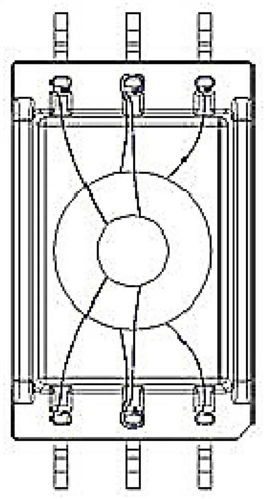
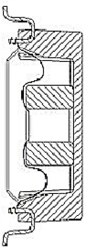
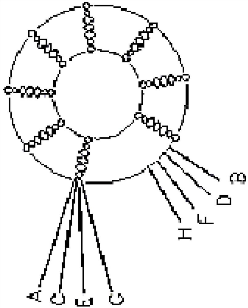
[0046] Please refer to Figure 1 to Figure 15 As shown, it shows the specific structure of various preferred embodiments of the present invention, including a PCB wire package 10, and the PCB wire package 10 has a first PCB integrated board 11 and a second PCB integrated board that are stacked and connected. 12. The first PCB integrated board 11 and the second PCB integrated board 12 both include a 4N layer PCB coil 20 and a 4N-1 layer PCB substrate 30 stacked up and down, and the N is an integer greater than or equal to 1; Each layer of PCB substrate 30 in the first PCB integrated board 11 and the second PCB integrated board 12 is separated between two adjacent layers of PCB coils 20, and the PCB coil 20 is printed on the PCB substrate 30 in a spiral shape. superior;

[0047] The two ends of the first PCB integrated board 11 and the second PCB integrated board 12 are correspondingly provided with three first through holes 101, and the middle is correspondingly provided with ...


PUM


Abstract

The invention relates to a planar transformer. The planar transformer comprises a PCB coil, the PCB coil is provided with a first PCB integrated board and a second PCB integrated board which are connected in a stacked mode, each of the first PCB integrated board and the second PCB integrated board comprises 4N layers of PCB coils and 4N-1 layers of PCB substrates, wherein the 4N layers of PCB coils and the 4N-1 layers of PCB substrates are stacked along a vertical direction, wherein N is an integer larger than or equal to 1; each layer of PCB substrate in the first PCB integrated board and the second PCB integrated board is arranged between two adjacent layers of PCB coils, and the PCB coils are printed on the PCB substrates in a vortex line shape. The PCB coils are printed on the PCB substrates, so that the winding process is omitted, the product characteristic consistency and high quality requirements can be met through standard industrial production, and the production efficiency is improved; the PCB coils are printed on the PCB substrates, so that the strength of welding points of the PCB coils is improved; the PCB coils are connected through corresponding through holes to form primary coils and secondary coils; and for a high-frequency transformer, a magnetic core does not need to be arranged, so that the drop resistance of the high-frequency transformer product is improved.

Description

technical field [0001] The invention relates to the technology in the field of transformers, in particular to a planar transformer. Background technique [0002] Traditional transformers such as Figure 1 to Figure 4 As shown, it adopts a circular magnetic core winding structure. The winding process is troublesome and the efficiency is limited. At the pin, the wire and the metal pin are connected by soldering tin. This soldering point is the product The weakest part, the failure of the product is mainly concentrated here; and for high-frequency transformers, it must use magnetic cores, because the magnetic cores are relatively brittle and easy to break, resulting in low drop resistance of the entire high-frequency transformer product. [0003] Therefore, it is necessary to improve the existing transformers. Contents of the invention [0004] In view of this, the present invention aims at the deficiencies in the prior art, and its main purpose is to provide a planar transf...

Claims


Application Information

Patent Timeline
IPC IPC(8): H01F27/28
CPCH01F27/2804H01F2027/2809
Inventor 赵社社周衡山王永刚张春雷
Owner DONGUAN PULSE ELECTRONICS CO LTD
Why Eureka
Try Eureka