Cylindrical steel shell battery and manufacturing method thereof

A profiled steel and battery technology, applied in the field of new energy vehicle energy storage power batteries, can solve the problems of low manufacturing environment dew point, difficult equipment realization, complex manufacturing process, etc., to reduce inactive material space, improve volume specific energy and weight High specific energy and production efficiency

Pending Publication Date: 2021-12-17
贵阳比耐新能源科技有限公司
View PDF0 Cites 7 Cited by
  • Summary
  • Abstract
  • Description
  • Claims
  • Application Information

AI Technical Summary

Problems solved by technology

In addition to the flexible packaging battery technology that satisfactorily solves the formation gas production and exhaust technology, the large cylindrical and square aluminum shell batteries are formed and exhausted after liquid injection, which makes the manufacturing process complicated and the corresponding equipment difficult to implement. In particular, during formation, negative pressure The seal between the nozzle and the liquid injection port is unreliable, which may easily cause electrolyte leakage and corrode the contacts of the equipment, resulting in a high failure rate of the equipment and frequent replacement of expensive contacts. At the same time, the manufacturing environment required by this process has a low dew point and the manufacturing higher cost

Method used


Image

  • Cylindrical steel shell battery and manufacturing method thereof
  • Cylindrical steel shell battery and manufacturing method thereof
  • Cylindrical steel shell battery and manufacturing method thereof

Examples


Embodiment 1

[0070] Example 1 ( Figure 1 to Figure 12 )

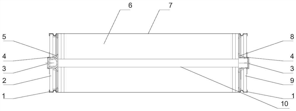
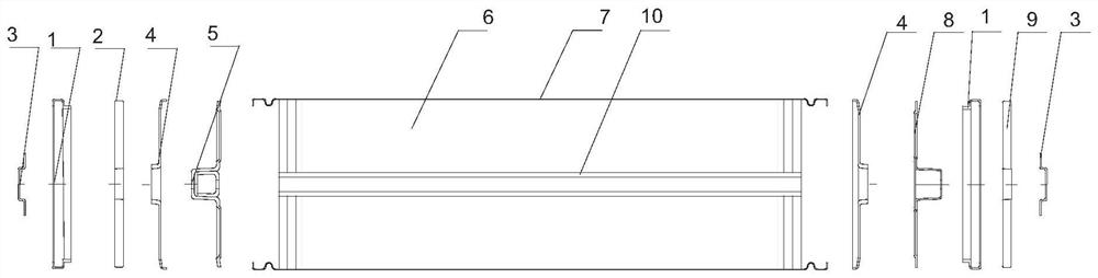
[0071] Such as Figure 1 to Figure 12 As shown, the cylindrical battery of the present invention includes a sealing ring 1, a positive electrode cover plate (aluminum) 2, a sealing sheet (aluminum) 3, a collector plate protective cover 4, a positive electrode collector plate assembly (aluminum) 5, and a full pole ear coil Core 6, Steel Shell 7; Negative Electrode Current Collector Assembly (Copper) 8, Negative Electrode Cover Plate (Copper / Copper-Aluminum Composite) 9, Center Tube 10.

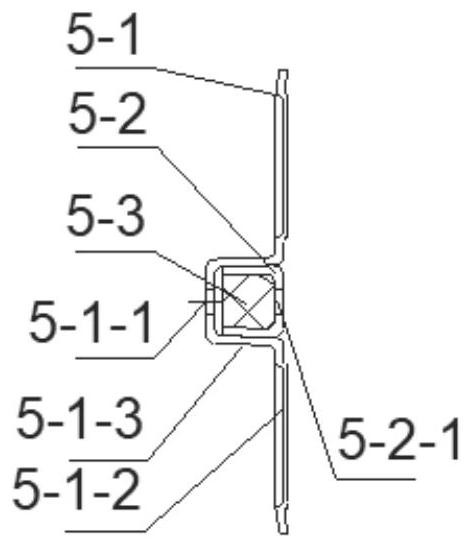
[0072] The structure of the positive / negative plate in the positive and negative collector plate assembly is as follows: image 3 , Figure 4 Shown is a U-shaped configuration.

Embodiment 2

[0073] Example 2 ( Figure 13 , Figure 14 )

[0074] Such as Figure 13 , Figure 14 As shown, the structure of the positive / negative plate in the positive and negative collector plate assembly is different, Figure 13 , Figure 14 For flat type. image 3 , Figure 4 It is a U-shaped structure. The above are only two forms of the positive / negative pole supporting plate, the purpose is to fix and compress the internal sealing member, and its structural shape is not limited to the above two forms.


PUM


Abstract

The invention relates to a cylindrical steel shell battery and a manufacturing method thereof, and belongs to the technical field of energy storage power batteries of new energy automobiles. The battery comprises a positive electrode cover plate, a positive electrode collector plate assembly, a full-tab roll core, a steel shell, a negative electrode collector plate assembly and a negative electrode cover plate, the negative electrode cover plate is located at the negative electrode end of the steel shell, the full-tab roll core welded with the positive electrode collector plate assembly and the negative electrode collector plate assembly is located in the steel shell, the positive electrode cover plate is located at the positive electrode end of the steel shell, the positive electrode collector plate assembly and the periphery of the positive electrode cover plate are sealed by laser welding, and the negative electrode collector plate assembly and the periphery of the negative electrode cover plate are sealed by laser welding. According to the invention, the large-current charge-discharge performance of the battery can be improved, battery accessories are simplified, the cost is reduced, the space of inactive substances in the battery is reduced, the volumetric specific energy and gravimetric specific energy of the battery are improved, a sealed formation process is realized, formation gas can be eliminated, the structure of formation equipment is simplified, and the environment control cost is reduced. The working environment is clean and pollution-free.

Description

technical field [0001] The application relates to a cylindrical steel case battery and a manufacturing method thereof, in particular to a cost-effective cylindrical steel case battery and a manufacturing method thereof, belonging to the technical field of energy storage power batteries for new energy vehicles. Background technique [0002] As a provider of power energy, power lithium or sodium-ion batteries have been widely used in new energy vehicles and energy storage. At present, the main technical routes of power batteries include three technical routes: large cylinder, soft pack and square. In addition to the flexible packaging battery technology that satisfactorily solves the formation gas production and exhaust technology, the large cylindrical and square aluminum shell batteries are formed and exhausted after liquid injection, which makes the manufacturing process complicated and the corresponding equipment difficult to implement. In particular, during formation, nega...

Claims


Application Information

Patent Timeline
Patent Type & Authority Applications(China)
IPC IPC(8): H01M4/72H01M50/533H01M50/538H01M50/609H01M10/52H01M10/058H01M10/0525H01M10/054
CPCH01M4/72H01M50/533H01M50/538H01M50/609H01M10/52H01M10/058H01M10/0525H01M10/054Y02E60/10Y02P70/50
Inventor 娄豫皖和祥运许祎凡
Owner 贵阳比耐新能源科技有限公司
Why Eureka
Try Eureka