
All-terrain telescopic rotary blade and using method thereof

An all-terrain and rotary tiller blade technology, applied in the field of rotary tiller, can solve the troublesome and inconvenient cleaning of the rotary tiller, and the inability of the rotary tiller to expand and contract elastically, so as to improve the effect of rotary tillage and avoid collisions

Active Publication Date: 2021-12-21
连云港市海林农业机械有限公司
View PDF10 Cites 1 Cited by
  • Summary
  • Abstract
  • Description
  • Claims
  • Application Information

AI Technical Summary

Problems solved by technology

[0005] The height of the existing rotary cultivating blade cannot be adjusted according to the needs when in use, and the existing rotary cultivating blade is fixedly connected with the knife frame. The shaft is easily entangled with sundries during use, which affects the effect of rotary tillage. The existing rotary tiller needs an external device to help move it, which is inconvenient. It is troublesome to clean the rotary tiller after use.

Method used


Image

  • All-terrain telescopic rotary blade and using method thereof
  • All-terrain telescopic rotary blade and using method thereof
  • All-terrain telescopic rotary blade and using method thereof

Examples


Embodiment 1

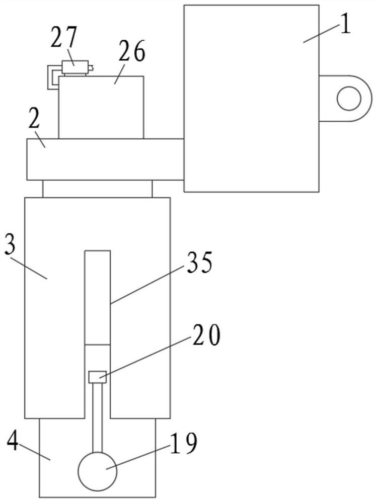
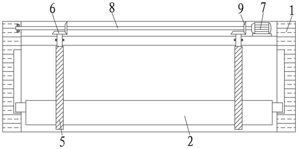
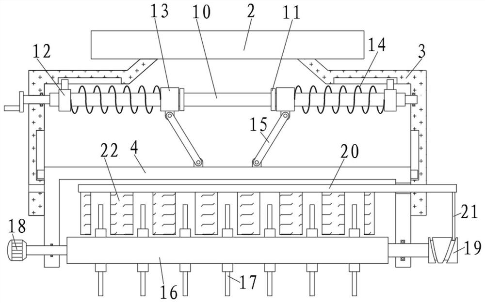
[0045] The all-terrain telescopic rotary tiller includes a mounting frame 1, a fixed plate 2 is slidably connected to the mounting frame 1, and a fixed frame 3 is fixedly installed on the bottom of the fixed plate 2 away from the mounting frame 1, and a knife frame 4 is slidably connected to the fixed frame 3 , and the cutter shaft 16 is rotatably connected to the tool holder 4, a second motor 18 is installed on one side of the tool holder 4, and the output end of the second motor 18 is connected with the cutter shaft 16, and a plurality of sets of blades are fixedly arranged on the outer side of the cutter shaft 16 17. A lifting mechanism is provided in the installation frame 1, and the lifting mechanism includes a threaded rod 5, a large bevel gear 6, a first motor 7, a cross bar 8, and a small bevel gear 9;

[0046] Two sets of threaded rods 5 are rotatably connected to the mounting frame 1, and the top of the threaded rods 5 is fixedly provided with a large bevel gear 6, th...

Embodiment 2

[0059] On the basis of embodiment 1,

[0060] A cutting mechanism matched with the blade 17 is also provided in the knife rest 4, and the cutting mechanism includes a cylindrical cam 19, a horizontal plate 20, a vertical bar 21, and a cutting knife 22;

[0061] One end of the knife shaft 16 extends out of the knife rest 4 and is fixedly connected with a columnar cam 19, and the inner top of the knife rest 4 is slidably connected with a horizontal plate 20, and the horizontal plate 20 extends out of the knife rest 4 and is fixedly provided with a vertical bar that matches the cylindrical cam 19. 21, and a plurality of groups of cutting knives 22 are fixedly arranged at the bottom of the horizontal plate 20.

[0062] One side of the fixing frame 3 is provided with a through groove 35 matching with the horizontal plate 20 , and gaps matching with the blades 17 are formed between the groups of cutting knives 22 .

[0063] The method of use of the present invention also includes: ...

Embodiment 3

[0065] On the basis of embodiment 2,

[0066] Both sides of the fixed frame 3 are also provided with a supporting mechanism, and the supporting mechanism includes a cylinder 28, a connecting plate 29, a connecting rod 30, a supporting rod 31, and a roller 32;

[0067] Cylinders 28 are installed on both sides of the fixed frame 3, and the output end of the cylinder 28 is fixedly provided with a connecting plate 29, the bottom two sides of the connecting plate 29 are rotatably connected with connecting rods 30, and the other ends of the connecting rods 30 are rotatably connected with support rods 31 , the support rod 31 is rotatably connected with the fixed frame 3 , and the bottom of the support rod 31 is provided with a roller 32 .

[0068] The method of use of the present invention also includes: when the device needs to move, start the cylinder 28, and the cylinder 28 drives the connecting rod 30 to rotate through the connecting plate 29. Since the supporting rod 31 is conne...


PUM


Abstract

The invention relates to the technical field of rotary blades, in particular to an all-terrain telescopic rotary blade which comprises a mounting frame, wherein a fixing plate is slidably connected into the mounting frame, a fixing frame is fixedly arranged at the bottom of the end, away from the mounting frame, of the fixing plate, a cutter frame is slidably connected into the fixing frame, a cutter shaft is rotationally connected into the cutter frame, a second motor is mounted on one side of the cutter frame, the output end of the second motor is connected with the cutter shaft, and multiple sets of blades are fixedly arranged on the outer side of the cutter shaft. The height of the blade can be adjusted according to needs, a buffer mechanism enables the blade to stretch out and draw back elastically, the resistance of a sliding block is adjusted through an adjusting block, the stretching elasticity of the blade on different soil texture is adjusted, the blade is prevented from being damaged in the using process, sundries wound on the outer side of the cutter shaft are cut off through a cutting knife, and the rotary tillage effect is improved; and the device is supported through supporting rods, the device is moved through rolling wheels, the device is convenient to move, so that the blade is flushed through swinging of a spray head, and cleaning is more sufficient through rotation of the blade.

Description

technical field [0001] The invention relates to the technical field of a rotary tiller, in particular to an all-terrain telescopic rotary tiller and a method for using the same. Background technique [0002] The rotary tiller is a driven soil tillage machine with rotating cutter teeth as the working part. It is a tiller that is matched with a tractor to complete plowing and harrowing. It has been widely used because of its strong soil breaking ability and flat surface after plowing. At the same time, it can chop up the root stubble buried below the surface, which is convenient for the seeder to operate and provides a good seed bed for later sowing. According to the configuration of the rotary tiller shaft, it is divided into two types: horizontal axis type and vertical axis type. The correct use and adjustment of the rotary tiller is very important to maintain its good technical status and ensure the quality of cultivation. It has the functions of breaking the bottom of the...

Claims


Application Information

Patent Timeline
Patent Type & Authority Applications(China)
IPC IPC(8): A01B49/02A01G25/09
CPCA01B49/027A01G25/092
Inventor 狄宁
Owner 连云港市海林农业机械有限公司
Learn More