Method and device for controlling dental implant

A technology for dental implants and instruments, which is applied in the fields of dental implants, dentistry, and dental restorations. It can solve problems such as the inability to control burs through observation, increase the difficulty of doctors' operations, and inconvenience dental implant surgery, so as to improve stability and improve implant stability. The effect of improving the accuracy of input, reducing the risk of surgery, and reducing the difficulty of operation

Active Publication Date: 2022-02-18
APEIRON SURGICAL CO LTD
View PDF5 Cites 0 Cited by
  • Summary
  • Abstract
  • Description
  • Claims
  • Application Information

AI Technical Summary

Problems solved by technology

[0004] The inventor found in the study of the prior art that in practical applications, since the implant is placed obliquely to the coronal plane, the drilling movement of the bur is also oblique to the coronal plane, and the movement of the bur cannot be controlled by observation during the operation. It brings inconvenience to the dental implant surgery, increases the difficulty of the doctor's operation, easily causes harm to the patient, and affects the surgical effect

Method used


Image

  • Method and device for controlling dental implant
  • Method and device for controlling dental implant
  • Method and device for controlling dental implant

Examples


Embodiment 1

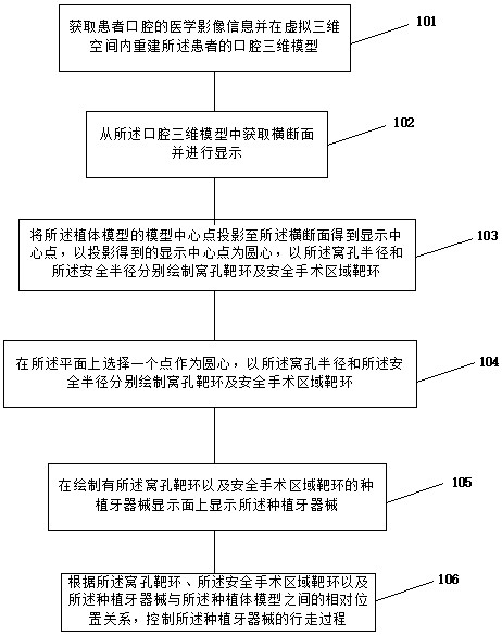
[0089] refer to figure 1 , which shows a structural block diagram of a dental implant device operation display method according to the present invention, which may specifically include:

[0090] Step 101: Obtain medical image information of a patient's oral cavity and reconstruct a three-dimensional model of the patient's oral cavity in a virtual three-dimensional space.

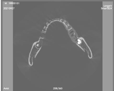
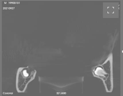
[0091] In the embodiment of the present invention, the medical image information of the oral cavity photographed and scanned by the patient can be obtained through the software system of the main control platform, and the medical image information can include CBCT (Cone Beam Computed Tomography, cone beam computerized tomography) ) images, including multiple layered scan images of the three-dimensional solid of the patient's oral cavity.

[0092] In the software system, a virtual three-dimensional space can be set, and based on the medical image information of the patient's oral cavity obtained above, the t...

Embodiment 2

[0189] Optionally, step 1062 in this embodiment of the present invention includes: substeps 1066-1067:

[0190] Sub-step 1066: Determine the first distance between the tip projection point of the tip of the dental implant instrument on the cross-section and the display center point;

[0191] Determine the tip projection point B (Bx, By) of the tip of the bur on the cross-section on the cross-section, and the coordinates of the display center point can be the projection point of point A on the cross-section calculated above, and the projection of point A The point coordinates are A(Ax, Ay), and the first distance LAB between the tip projection point and the display center point is calculated in the software system:

[0192] (Bx-Ax)²+(By-Ay)²=LAB²

[0193] Sub-step 1067: If the first distance is greater than the radius of the hole target ring, determine that the tip of the dental implant device deviates from the hole target ring.

[0194] According to the socket radius R1 obta...

Embodiment 3

[0203] refer to Figure 10 , shows a schematic structural view of a control device for a dental implant device in an embodiment of the present invention.

[0204] The dental implant device operating device 200 in the embodiment of the present invention includes: a model reconstruction module 210 , a display surface acquisition module 220 , a radius calculation module 230 , a target ring generation module 240 , a target ring drawing module 250 , and an instrument control module 260 .

[0205] The functions of each module and the interaction between each module are introduced in detail below.

[0206] A model reconstruction module 210, configured to acquire medical image information of the patient's oral cavity and reconstruct the patient's oral cavity three-dimensional model in a virtual three-dimensional space;

[0207] A display surface acquisition module 220, configured to acquire a cross-section from the three-dimensional model of the oral cavity and display it;

[0208] ...


PUM


Abstract

The invention provides a control method and device for a dental implant device, a surgical robot and a storage medium. The cross-section is acquired from a three-dimensional model of the oral cavity and displayed; the safety of the safe surgical area around the implant is determined according to the model parameters of the implant model. Radius and the hole radius of the implant socket for placing the implant; project the model center point of the implant model to the cross section to obtain the display center point, take the projected display center point as the center of the circle, and use the hole radius and The safety radius draws the target ring of the cavity and the target ring of the safe operation area respectively; the dental implant device is displayed on the display surface of the dental implant device with the target ring of the cavity and the target ring of the safe operation area; according to the target ring of the cavity and the target ring of the safe operation area The ring and the relative positional relationship between the dental implant device and the implant model control the walking process of the dental implant device. Thus, it is convenient to prevent the dental implant instrument from drilling into other organ tissues and deep dental nerve tissues.

Description

technical field [0001] The invention relates to the technical field of dental implants, in particular to a control method and device for dental implants. Background technique [0002] In dental implant surgery, the field of view in the oral cavity is non-direct and the space is narrow, so it is usually necessary to perform surgery with the help of image display. [0003] In the prior art, in the process of implanting the implant in the oral cavity, the doctor imports the patient's oral medical image through the software system, obtains the coronal image of the tooth according to the medical image, sets the implant position on the coronal image, and then The bur is driven by the robotic arm to drill holes at the planting position of the implant. During the above process, the software system above will display the positional relationship between the bur and the implant position on the coronal image in order to facilitate the doctor to observe the bur turning process. [0004...

Claims


Application Information

Patent Timeline
Patent Type & Authority Patents(China)
IPC IPC(8): A61C8/00A61C19/06
CPCA61C8/0089A61C19/06
Inventor 王迎智袁平徐高峰
Owner APEIRON SURGICAL CO LTD
Why Eureka
Try Eureka