Ultrathin hard alloy tool bit structure with center partition

A cemented carbide knife and cemented carbide technology, which is applied in other manufacturing equipment/tools, turbines, engine components, etc., can solve the problem of unstable quality of cemented carbide cutter heads, affecting the cutting quality of alloy cutter heads, and the hardness of cutter head alloys. Non-uniformity and other problems, to achieve the effect of good market promotion value, improved sintering stability, and convenient implementation

Pending Publication Date: 2021-12-21
林友平
View PDF0 Cites 0 Cited by
  • Summary
  • Abstract
  • Description
  • Claims
  • Application Information

AI Technical Summary

Problems solved by technology

Due to the design of the number of layers in the infrared temperature measuring hole of the six-layer mold, the temperature at the center point is too high, resulting in the blue marks of over-sintering on the heads of many high-melting point-to-head formulas, and most of them are concentrated in the center position. The blu

Method used


Image

  • Ultrathin hard alloy tool bit structure with center partition
  • Ultrathin hard alloy tool bit structure with center partition
  • Ultrathin hard alloy tool bit structure with center partition

Examples


Embodiment 1

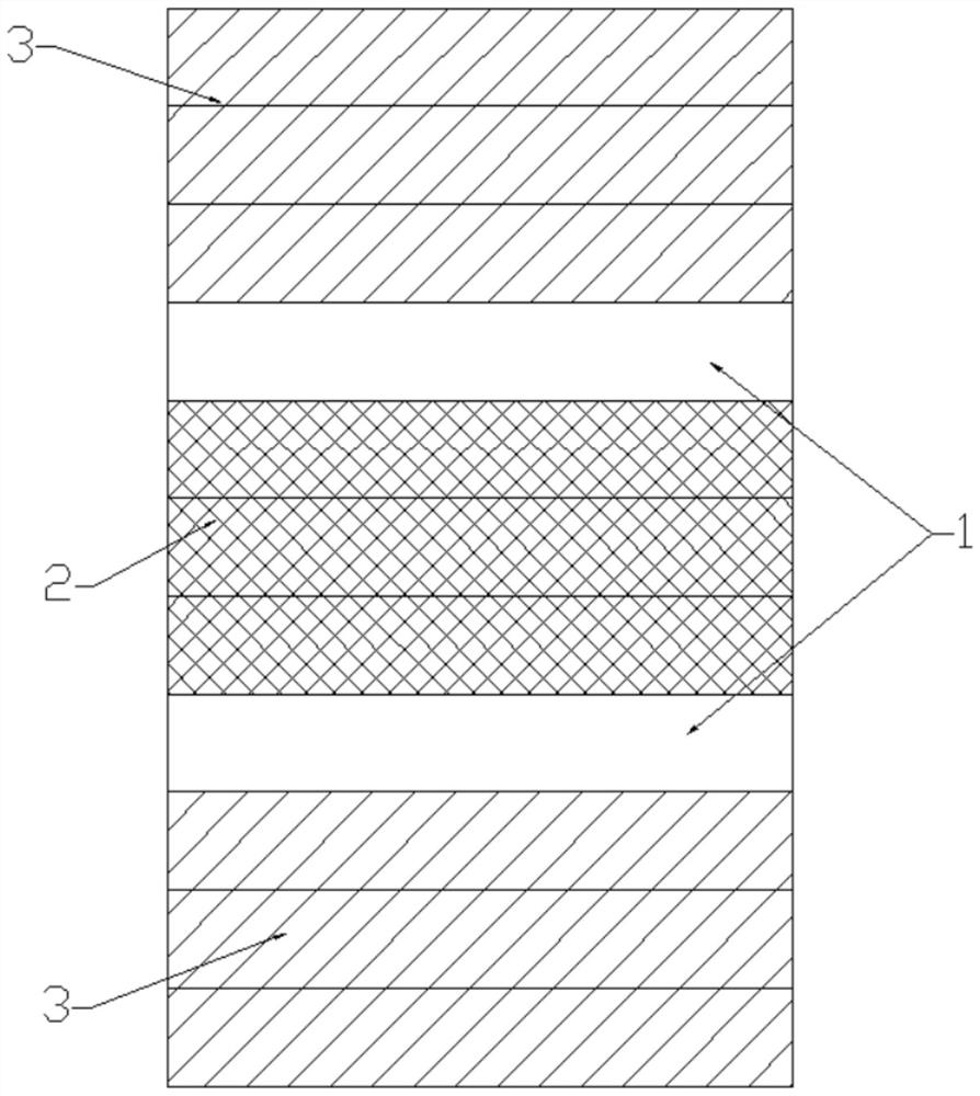
[0019] As shown in the figure, an ultra-thin cemented carbide cutter head structure with a central partition includes an even number of cemented carbide cutter head layers 1, and graphite is arranged between the two adjacent cemented carbide cutter head layers 1 in the middle. Graphite mold indenters 3 are provided on the outer sides of the mold center partition layer 2 and the outermost two cemented carbide cutter head layers 1 .

[0020] The number of the cemented carbide cutter head layer 1 is two layers, the graphite mold center partition layer 2 is located between the two cemented carbide cutter head layers 1, and the graphite mold indenter 3 is located between the two cemented carbide cutter heads. Both sides of the head layer 1.

Embodiment 2

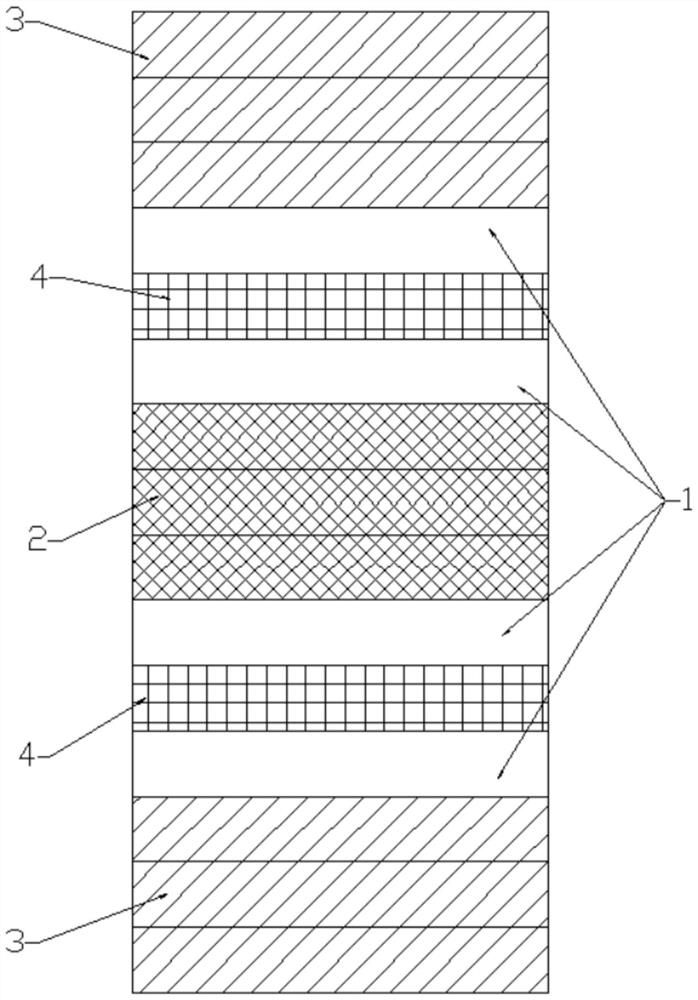
[0022] As shown in the figure, an ultra-thin cemented carbide cutter head structure with a central partition includes an even number of cemented carbide cutter head layers 1, and graphite is arranged between the two adjacent cemented carbide cutter head layers 1 in the middle. Graphite mold indenters 3 are provided on the outer sides of the mold center partition layer 2 and the outermost two cemented carbide cutter head layers 1 .

[0023] The quantity of described cemented carbide cutter head layer 1 is four layers, and graphite mold layer 4 is arranged between the cemented carbide cutter head layers 1 on the same side of described graphite mold central partition layer 2, and described graphite mold central partition layer 2 The two sides are successively a cemented carbide cutter head layer 1, a graphite mold layer 4, a cemented carbide cutter head layer 1, and a graphite mold indenter 3.

Embodiment 3

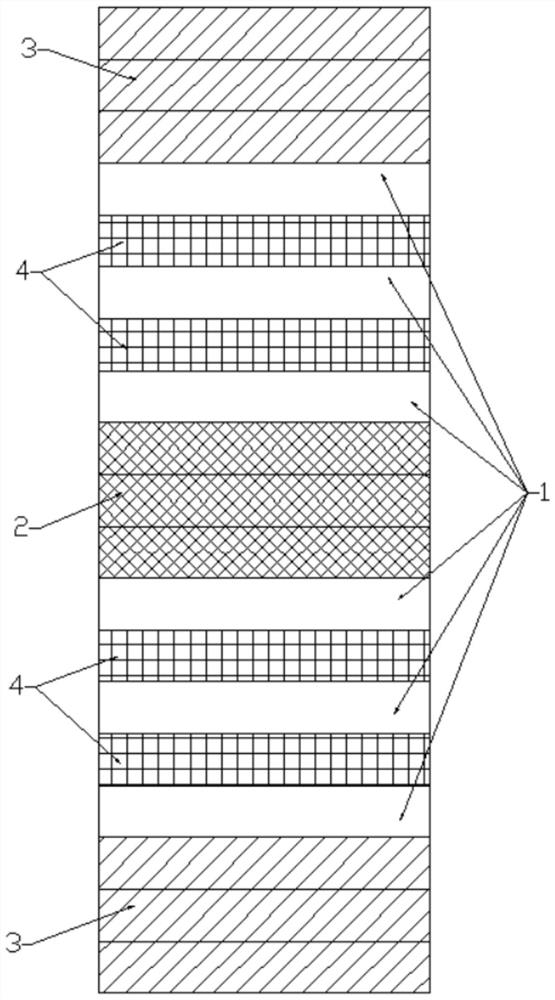
[0025] As shown in the figure, an ultra-thin cemented carbide cutter head structure with a central partition includes an even number of cemented carbide cutter head layers 1, and graphite is arranged between the two adjacent cemented carbide cutter head layers 1 in the middle. Graphite mold indenters 3 are provided on the outer sides of the mold center partition layer 2 and the outermost two cemented carbide cutter head layers 1 .

[0026] The number of the cemented carbide cutter head layer 1 is six layers, and the graphite mold center partition layer 2 is provided with a graphite mold layer 4 between the cemented carbide cutter head layers 1 on the same side of the graphite mold center partition layer 2 The two sides are successively a cemented carbide cutter head layer 1, a graphite mold layer 4, a cemented carbide cutter head layer 1, a graphite mold layer 4, a cemented carbide cutter head layer 1, and a graphite mold indenter 3.

[0027] When the present invention is actu...


PUM


Abstract

The invention discloses an ultrathin hard alloy tool bit structure with a center partition. The ultrathin hard alloy tool bit structure comprises an even number of hard alloy tool bit layers, a graphite mold center partition layer is arranged between the two middlemost adjacent hard alloy tool bit layers, and graphite mold pressing heads are arranged on the outer sides of the two outermost hard alloy tool bit layers. Compared with the prior art, the ultrathin hard alloy tool bit structure has the advantages that the structure is simple, implementation is convenient, the center partition layer is used for avoiding a center point high-temperature area of a graphite mold, the center partition layer adopts a graphite material with higher density, erosion of center high temperature to a center layer tool bit is effectively avoided, the center layer is removed, the center point of the sintered and fired hard alloy tool bit is burnt blue, the sintering stability of the hard alloy tool bit is greatly improved, the alloying degree is more uniform and higher, and the optimal and most reasonable hardness of the hard alloy tool bit is guaranteed. Good market popularization value is realized.

Description

technical field [0001] The invention relates to the technical field of making metal cutting tools, in particular to an ultra-thin cemented carbide cutter head structure with a central partition. Background technique [0002] Ultra-thin (thickness below 4.0) carbide cutter head, the 6-layer mold used for production is popular in the market at present, the biggest advantage is to increase the output on the basis of the traditional two-layer mold and 4-layer mold, and the six-layer mold is improving At the same time as the output, it also has fatal flaws. Due to the design of the number of layers in the infrared temperature measuring hole of the six-layer mold, the temperature at the center point is too high, resulting in the blue marks of over-sintering on the heads of many high-melting point-to-head formulas, and most of them are concentrated in the center position. The blue scorched alloy cutter head is the embodiment of over-sintering. The quality of such a cemented carbid...

Claims


Application Information

Patent Timeline
IPC IPC(8): B22F5/00B22F3/00B22F3/14
CPCB22F5/00B22F3/003B22F3/14B22F2005/001
Inventor 林友平
Owner 林友平
Why Eureka
Try Eureka