Separation equipment and method for micro-plastic in plateau lake sediments

A technology for separating equipment and sediments, applied in centrifuges and other directions, can solve problems such as inconvenience, high cost, and inability to classify and separate microplastics, and achieve the effects of improving accuracy, saving production costs, and improving filtering effect.

Pending Publication Date: 2021-12-24
GUIZHOU UNIV
View PDF7 Cites 2 Cited by
  • Summary
  • Abstract
  • Description
  • Claims
  • Application Information

AI Technical Summary

Problems solved by technology

With the expansion of the field of human activities and the continuous increase of material demand, the intensity of human intervention and utilization of plateau lakes is also increasing, resulting in a large accumulation of microplastics in plateau lake sediments. Because microplastics are difficult to degrade and often pass through The secondary effect will produce unpredictable potential hazards, so it is urgent to separate the microplastics in the sediment to prevent the microplastics from causing greater pollution to the environment. The current separation method is mainly the flotation method in the laboratory, but for There are few reports on the separation equipment and methods of microplastics in plateau lake sediments, and the current methods cannot classify and separate microplastics by size, which is not convenient for subsequent in-depth research. At the same time, the flotation method requires the use of corresponding saturated solutions. ,higher cost

Method used


Image

  • Separation equipment and method for micro-plastic in plateau lake sediments
  • Separation equipment and method for micro-plastic in plateau lake sediments
  • Separation equipment and method for micro-plastic in plateau lake sediments

Examples


Embodiment 1

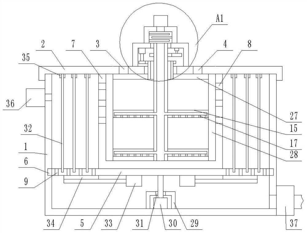
[0035] refer to Figure 1-2 , this embodiment discloses a separation device for microplastics in plateau lake sediments, including: a separation cylinder 1, the top surface of the separation cylinder 1 is open, and the top surface of the separation cylinder 1 is detachably connected with an end cover 2, the end cover 2 There is a stirring device on the top, the top surface of the end cover 2 is provided with a ventilation hole 3 and a feeding hole 4, and the end cover 2 is provided with a centrifugal device;

[0036] The centrifugal device includes a rotating mechanism, the rotating mechanism is arranged at the bottom of the inner cavity of the separation cylinder 1, and the top surface of the rotating mechanism is fixedly connected with a centrifugal plate 5, and a first sealed bearing 6 is arranged between the peripheral wall of the centrifugal plate 5 and the inner wall of the separation cylinder 1, and the centrifugal plate 5 The bottom surface and the bottom of the inner ...

Embodiment 2

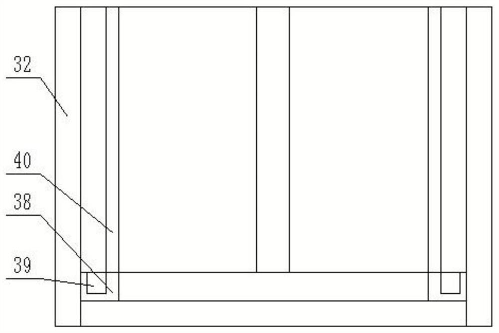
[0067] refer to Figure 3-4In order to facilitate the collection of microplastic particles attached to the annular filter screen 32 after completing the filtration, a collection mechanism is provided. The collection mechanism includes a collection ring 38, the outer wall of the collection ring 38 abuts against the bottom of the inner wall of the annular filter screen 32, and the collection ring 38 An annular collection groove 39 is provided on the top surface, and a plurality of lifting rods 40 are fixedly connected to the top surface of the collection ring 38;

[0068] After the filtration is completed, take out the annular filter 32 and the collection mechanism, pull the lifting rod 40 upward, and during the upward movement of the collection ring 38, the microplastic particles attached to the annular filter 32 will be collected and stored in the annular collection tank 39 , improving the collection efficiency of microplastic particles.

Embodiment 3

[0070] refer to Figure 5 , the set mud pumping mechanism includes a mud pumping shell 41 consolidated on the top surface of the rotating shell, and a mud pumping pipe 42 is arranged in the mud pumping shell 41, and one end of the mud pumping pipe 42 is connected to the rotary motor 30 is fixedly connected to the output shaft, the top of the mud pumping pipe 42 passes through the top surface of the mud pumping shell 41 and communicates with the bottom of the inner cavity of the centrifugal cylinder 7, and the mud pumping pipe 42 is fixedly connected to the centrifugal plate 5 A first dredging pump 43 is fixedly connected to the top of the cavity of the dredging pipe 42, and one end of a dredging tube 44 is communicated with the side of the dredged shell 41, and the other end of the dredged tube 44 runs through the separation cylinder 1. The outer wall communicates with the second dredge pump 45.

[0071] After the supernatant is extracted, the microplastic separation test is ...


PUM


Abstract

The invention discloses separation equipment and method for micro-plastic in plateau lake sediments. The separation equipment comprises a separation cylinder, wherein the top surface of the separation cylinder is open, an end cover is detachably connected to the top surface of the separation cylinder, a stirring device is arranged on the end cover, a vent hole and a feeding hole are formed in the top surface of the end cover, and a centrifugal device is arranged in the end cover; the centrifugal device comprises a rotating mechanism, the rotating mechanism is arranged at the bottom of an inner cavity of the separation cylinder, a centrifugal plate is fixedly connected to the top surface of the rotating mechanism, a first sealing bearing is arranged between the peripheral wall of the centrifugal plate and the inner wall of the separation cylinder, a liquid storage cavity is formed between the bottom surface of the centrifugal plate and the bottom of the inner wall of the separation cylinder, a centrifugal cylinder is fixedly connected to the center of the top surface of the centrifugal plate, a plurality of liquid outlet holes are formed in the top of the centrifugal cylinder at equal intervals in the circumferential direction, a plurality of filtering mechanisms are sequentially arranged outside the centrifugal cylinder in a sleeving mode, the inner cavity of the centrifugal cylinder is divided into a plurality of filtering cavities by the filtering mechanisms, a plurality of liquid discharging holes are formed in the centrifugal plate, and the filtering cavities communicate with the liquid storage cavity through the liquid discharging holes; and a plurality of water discharging mechanisms are arranged on the bottom surface of the centrifugal plate at equal intervals in the circumferential direction.

Description

technical field [0001] The invention relates to the technical field of separation of microplastics, in particular to a separation device and method for microplastics in plateau lake sediments. Background technique [0002] Microplastics are a new type of environmental pollutants, which refer to plastic particles and textile fibers with a particle size of less than 5mm. Microplastics are small and easy to be ingested by aquatic organisms, and may also become carriers of other pollutants. In recent years, microplastic pollution has received widespread attention around the world. Microplastics are divided into two categories: primary microplastics and secondary microplastics. Primary microplastics refer to industrial products of plastic particles discharged into the water environment through rivers, sewage treatment plants, etc., such as microplastic particles contained in cosmetics or used as Plastic granules and resin granules of industrial raw materials, secondary microplas...

Claims


Application Information

Patent Timeline
IPC IPC(8): B04B5/00B04B7/08B04B7/00B04B15/00B04B15/06
CPCB04B5/00B04B7/08B04B7/00B04B15/00B04B15/06Y02W30/62
Inventor 张珍明张家春曾宪平刘盈盈罗文敏吴先亮黄先飞
Owner GUIZHOU UNIV
Why Eureka
Try Eureka