Blowing-type sintering waste heat recovery and agglomeration device and method

A waste heat recovery and blasting device technology, applied in waste heat treatment, lighting and heating equipment, furnace components, etc., can solve problems such as easy blocking of grate bars, low drum, sintering, etc. Strength-enhancing effect

Pending Publication Date: 2021-12-24
阜新建兴金属有限公司
View PDF0 Cites 0 Cited by
  • Summary
  • Abstract
  • Description
  • Claims
  • Application Information

AI Technical Summary

Problems solved by technology

[0004] In order to be able to solve metallurgical solid waste materials, when the briquette calcination method or the traditional sintering machine with a sintering machine are used for production, the sintered ore products have poor strength after thermal reaction, low drum, high ferrous iron, and easy to block during sintering. Grate bars, sticking to the rotor of the main exhaust fan, high cost of sintering and agglomeration, the present invention provides a blasting sintering waste heat recovery agglomeration device and method
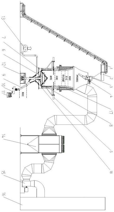
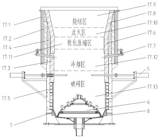
This method combines the hydraulic crushing gun with the cone crusher, and the cold air from bottom to top passes through the high-temperature sintered block, preheating the cold air into hot air, using hot air for sintering, recycling and utilizing the waste heat of the high-temperature sintered block, and solving the technical problem of sintering metallurgical solid waste materials

Method used


Image

  • Blowing-type sintering waste heat recovery and agglomeration device and method
  • Blowing-type sintering waste heat recovery and agglomeration device and method
  • Blowing-type sintering waste heat recovery and agglomeration device and method

Examples


Embodiment Construction

[0019] In order to make the objects, technical solutions, and advantages of the present invention more clearly, the technical solutions in the embodiments of the present invention will be described in contemplation in the embodiment of the present invention. It is an embodiment of the invention, not all of the embodiments. Components of the embodiments of the present invention described and illustrated in the drawings herein can be arranged and design in various configurations. Thus, the following detailed description of the embodiments of the invention in the drawings is not intended to limit the scope of the invention claims, but only the selected embodiments of the present invention are shown. Based on the embodiments in the present invention, all other embodiments obtained without creative labor are not made in the premise of creative labor.

[0020] It should be noted that similar reference numerals and letters represent the similar items in the following figures, and therefo...


PUM


Abstract

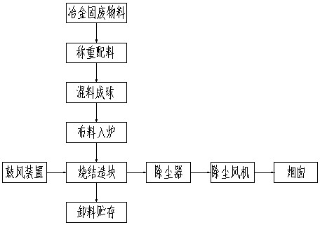
The invention provides a blowing-type sintering waste heat recovery and agglomeration device and method. The device comprises a material distributing device, a crushing device, a blowing-type waste heat recovery sintering furnace, a blowing device, a discharging device and a dust removing device. The crushing device is used for continuously and uniformly crushing sintered blocky materials from the inside of the furnace. The blowing device needs to continuously blow air in the sintering process, cold air is heated into hot air by crushed hot sinter, and high-temperature sintering waste heat is recycled. A hydraulic crushing gun and a cone crusher are combined, cold air from bottom to top passes through high-temperature sintered blocks, the cold air is preheated into the hot air, the hot air is used for sintering, waste heat of the high-temperature sintered blocks is recycled, the use amount of a reducing agent is reduced, gas ignition is not needed, FeO is fully reduced, and ferrous iron in sinter is reduced. A softening compression area extrudes molten sinter, so that the strength of the sinter is enhanced, and the problems that a grid section is prone to being blocked and a rotor of a main exhaust fan is prone to suffering from adhesion are solved. The method is suitable for being used as the blowing-type sintering waste heat recovery and agglomeration method.

Description

Technical field [0001] The present invention relates to metallurgical solid waste materials in the field of recovery, and more particularly to a blast sintered residual heat recovery block device and method. Background technique [0002] During the production process, the production of solid waste materials such as dust removal, steel slag, sulfate, zinc slag, sulfur-containing, potassium, sodium, and zinc are high, and an iron element of about 50%. At present, the recovery of these solid waste materials, most of which uses a pressurized burning method or a conventional belt burner air blown method. The strength of the pressurin calcination method is low, and it is fragile, which is fragile, is not conducive to smelting recovery; conventional belt burner air blown sintering method, because solid waste materials contain sulfur, potassium, sodium, zinc, etc. harmful element Therefore, when sintering is severe, while the main exhaustion rotor is easy to bond the volatile, break the ...

Claims


Application Information

Patent Timeline
Patent Type & Authority Applications(China)
IPC IPC(8): F27D17/00
CPCF27D17/004F27D17/008Y02P10/25
Inventor 王建康林建强
Owner 阜新建兴金属有限公司
Why Eureka
Try Eureka