Fine treatment device for fiber reinforced polymer composite material

A fiber-reinforced, composite material technology is applied in the field of fiber-reinforced polymer composite material fine processing devices to achieve the effects of ensuring accuracy, facilitating overhaul and maintenance, and facilitating disassembly and installation

Active Publication Date: 2021-12-28
QINGDAO TIPONT CORD
View PDF7 Cites 0 Cited by
  • Summary
  • Abstract
  • Description
  • Claims
  • Application Information

AI Technical Summary

Problems solved by technology

[0005] In order to solve the technical problems existing in the background technology, the present invention proposes a fine processing device for fiber-reinforced polymer composite materials, which solves the problem of pretreatment of fiber-reinforced polymer raw materials and at the same time processes the dust generated by crushing, Furthermore, the precision of raw material processing is ensured. At the same time, the device has ingenious structure, reasonable design, simple operation, strong practicability, and is suitable for wide promotion.

Method used


Image

  • Fine treatment device for fiber reinforced polymer composite material
  • Fine treatment device for fiber reinforced polymer composite material
  • Fine treatment device for fiber reinforced polymer composite material

Examples


Embodiment 1

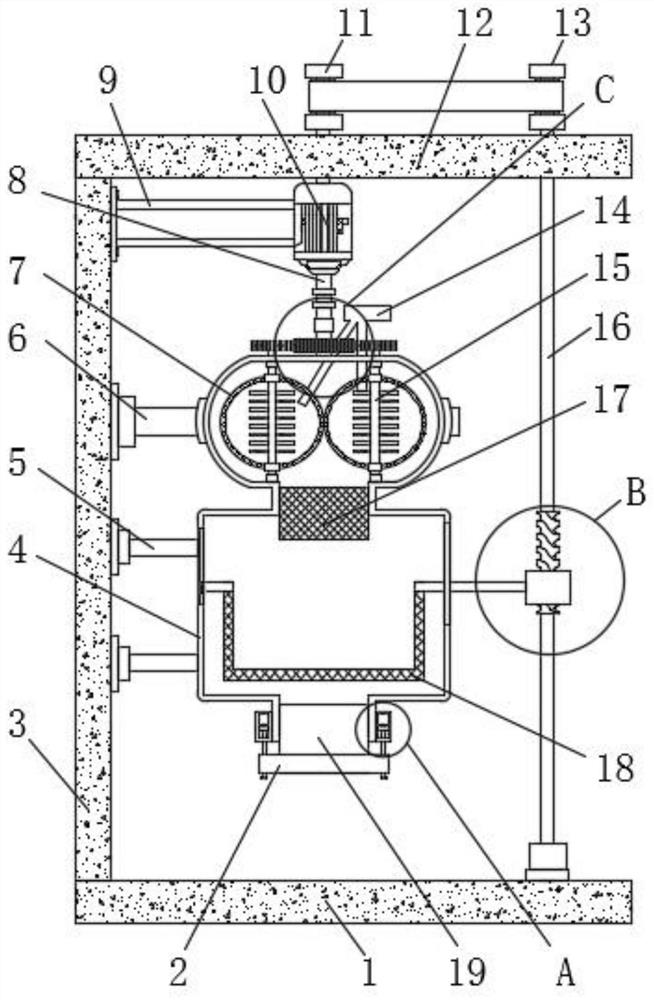
[0042] Embodiment 1: as figure 1 As shown, a fine processing device for fiber-reinforced polymer composite materials proposed by the present invention includes a base 1, a support column 3 is welded on the left side of the top of the base 1, and two first supports are welded on the right bottom of the support column 3 frame 5, the right end of the first support frame 5 is welded with a processing box body 4, the left side inner wall of the processing box body 4 is slidably connected with a sieve bucket 18, and the right end of the sieve bucket 18 is welded with a Movable bar 20, two pulverizing rollers 15 are sleeved on the top of processing box body 4, and one end of pulverizing roller 15 is positioned at processing box body 4 inside and one side inner wall of processing box body 4 is rotationally connected, and the outer ring of pulverizing roller 15 is welded with The tops of the crushing tank 7 and the crushing roller 15 are welded with a first gear 24 .

Embodiment 2

[0043] Embodiment 2: as figure 1 , Figure 4 As shown, the top of the processing box 4 is sleeved with a feed pipe 14 that runs through and extends into the crushing tank 7, and the outer ring of the crushing roller 15 is welded with a plurality of crushing blades arranged in a rectangular array. The top of the outer ring is welded with a second support frame 6, the top of the processing box 4 is rotatably connected with a first gear 24, the top of the first gear 24 is welded with a flange tube 23, and the top of the flange tube 23 is welded with a rotating shaft 8 to support The top right side of the column 3 is fixed with a third support frame 9 by bolts, and the end of the third support frame 9 away from the support column 3 is welded with a biaxial motor 10, and the bottom output end of the biaxial motor 10 is far away from the rotating shaft 8 One end of 23 is welded, and the middle part of both sides inner walls of processing box body 4 is welded with filter box 17.

Embodiment 3

[0044] Embodiment 3: as figure 1 and Figure 7-9 As shown, the rear side of the processing box 4 is provided with a dust removal box 32, a connecting pipe 33 is provided between the dust removal box 32 and the processing box 4, and the side wall of the dust removal box 32 is provided with a through hole 3201. One end of the connecting pipe 33 runs through the through hole 3201 and communicates with the interior of the dust removal box 32. The side wall of the miscellaneous removal box 32 is provided with a mechanism for easy disassembly. The mechanism for easy removal includes a positioning plate 35, a guide plate 36, a limit plate 37, and a sleeve spring 38 , insertion rod 39 and card slot 3401, the positioning plate 35 is fixedly installed on the side wall of the dust removal box 32, one end of the guide plate 36 runs through the positioning plate 35 and is slidingly connected with it, and the insertion rod 39 is fixedly installed, and the guide plate 36 is another One end ...


PUM


Abstract

The invention discloses a fine treatment device for fiber reinforced polymer composite material. The fine treatment device comprises a base, wherein a supporting column is welded to the left side of the top of the base; a processing box is arranged at the right side of the supporting column; a dust removal box is arranged at the rear side of the processing box; a connecting pipe is arranged between the dust removal box and the processing box; a convenient-to-disassemble mechanism is arranged on the side wall of the impurity removal box and comprises a positioning plate, a guide plate, a limiting plate, a sleeve spring, an inserting rod and a clamping groove; the positioning plate is fixedly installed on the side wall of the dust removal box; one end of the guide plate penetrates through the positioning plate and is glidingly connected with the positioning plate; in addition, the inserting rod is fixedly installed; the limiting plate is fixedly installed at the other end of the guide plate; the outer side of the guide plate is sleeved with a sleeve spring; the outer side of the connecting pipe is sleeved with a limiting block; a clamping groove is formed in the side wall of the limiting block; and the inserting rod is connected with the clamping groove in a clamped mode. Dust generated by crushing is treated, so that the connecting pipe is convenient to dismount and mount, and the overhaul and the maintenance are convenient.

Description

technical field [0001] The invention relates to the field of processing fiber-reinforced polymer composite materials, in particular to a fine processing device for fiber-reinforced polymer composite materials. Background technique [0002] Fiber-reinforced composite material (FRP) is a composite material formed by reinforcing fiber materials, such as glass fiber, carbon fiber, aramid fiber, etc., and matrix materials through winding, molding or pultrusion molding processes. , common fiber reinforced composite materials are divided into: glass fiber reinforced composite materials (GFRP), carbon fiber reinforced composite materials (CFRP) and aramid fiber reinforced composite materials (AFRP). Large modulus, material properties can be designed, good corrosion resistance and durability, and the thermal expansion coefficient is similar to that of concrete. These characteristics make FRP materials suitable for modern structures that are large-span, towering, heavy-duty, light-wei...

Claims


Application Information

Patent Timeline
Patent Type & Authority Applications(China)
IPC IPC(8): B02C18/10B02C18/24B02C18/16B02C23/14B02C23/24
CPCB02C18/10B02C18/24B02C18/16B02C23/14B02C23/24Y02W30/62
Inventor 左文强
Owner QINGDAO TIPONT CORD
Why Eureka
Try Eureka