Gear scrap cleaning device

A technology for cleaning devices and gears, used in gear tooth manufacturing devices, belts/chains/gears, gear teeth, etc., can solve the problems of scattered waste, multiple wastes, and difficulty in cleaning iron filings, and achieve clean adsorption. , the effect of high efficiency

Pending Publication Date: 2021-12-31
CHONGQING RUNYUE MACHINERY CO LTD
View PDF13 Cites 0 Cited by
  • Summary
  • Abstract
  • Description
  • Claims
  • Application Information

AI Technical Summary

Problems solved by technology

However, when the gear is cut on the milling machine, a lot of waste will be generated, which will cause a large amount of waste to be scattered on the workbench and the ground, and it will stop working until the waste generated by the milling machine has accumulated to a certain extent, and then Manual cleaning and collection of those iron filings, it is more difficult to clean up the iron filings, which affects work efficiency

Method used


Image

  • Gear scrap cleaning device
  • Gear scrap cleaning device
  • Gear scrap cleaning device

Examples


Embodiment 1

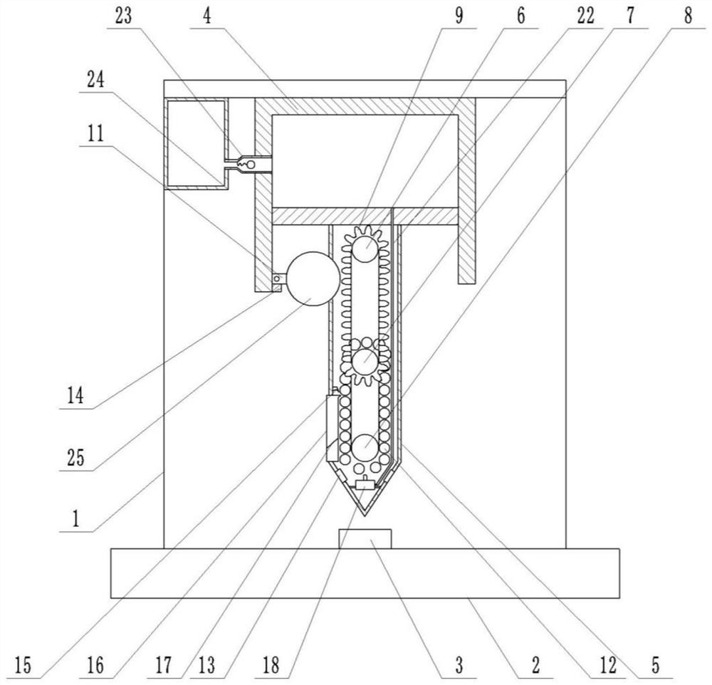
[0030] Example 1 is basically as attached Figure 1-4 shown:

[0031] A gear scrap cleaning device, comprising a frame 1, a worktable 2 is arranged on the frame 1, a hydraulic cylinder 4 is arranged on the frame 1, a cutter 5 is installed on the piston of the hydraulic cylinder 4, and the cutter 5 is arranged on the There is a waste cleaning device; the worktable 2 is arranged under the cutter 5, the worktable 2 is used to store the gear workpiece 3, and the hydraulic cylinder 4 is used to drive the cutter 5 to move up and down, thereby completing the cutting of the gear workpiece 3.

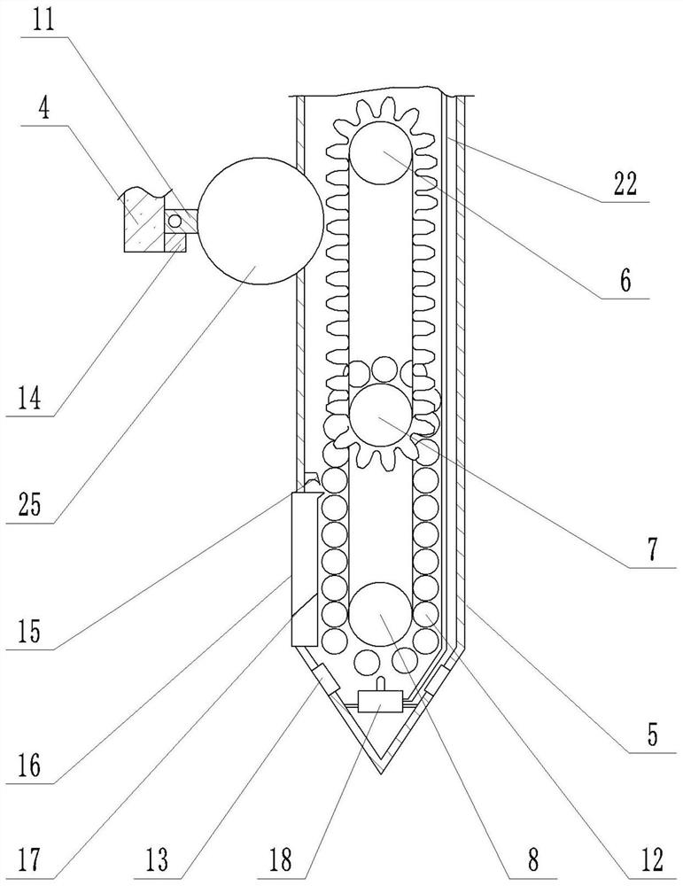
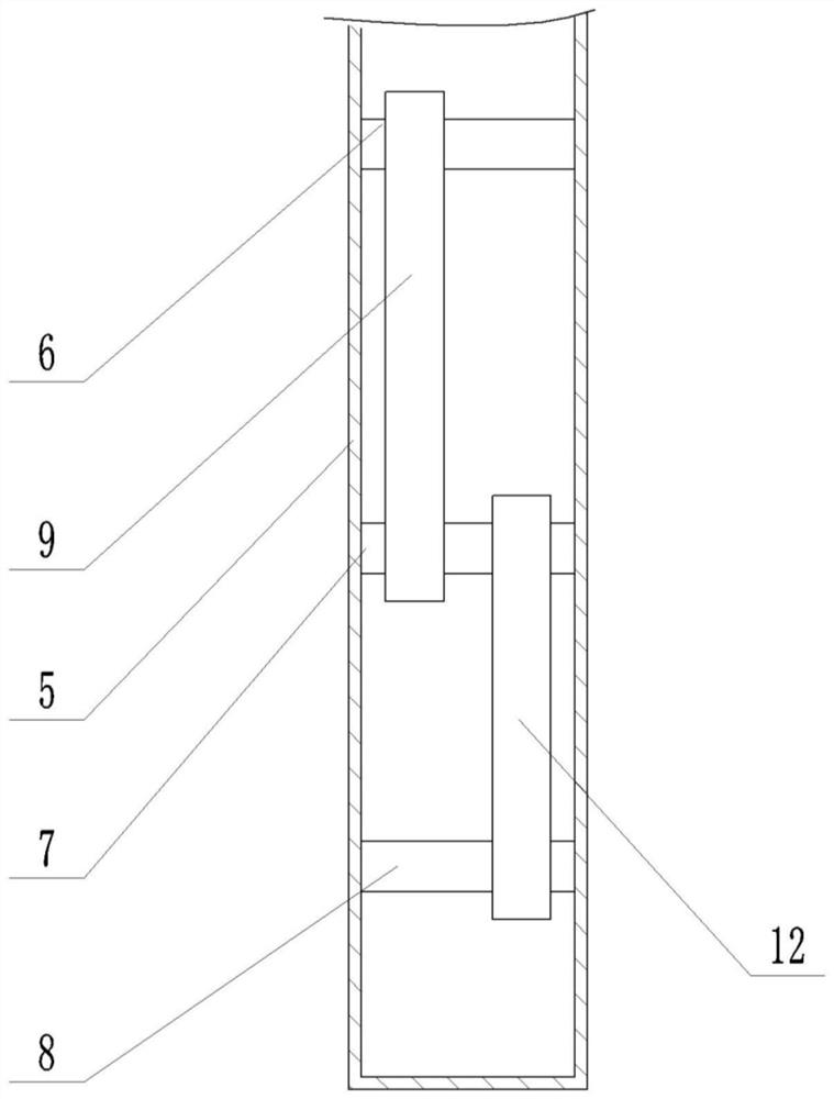
[0032] The waste cleaning device includes a first rotating shaft 6, a second rotating shaft 7, a third rotating shaft 8 and a gear 25. The first rotating shaft 6, the second rotating shaft 7 and the third rotating shaft 8 are rotatably arranged on the side walls at both ends of the cutter 5, The first rotating shaft 6 and the second rotating shaft 7 are connected with a chain 9, the cutter 5 is...

Embodiment 2

[0049] The difference between this embodiment 2 and the embodiment 1 is that, as shown in the appendix Image 6 shown:

[0050] Also includes a storage mechanism, the storage mechanism includes a storage rack 26 and a moisture monitoring assembly, the storage rack 26 is sequentially provided with a storage frame 27 for storing the gear workpiece 3 from top to bottom,

[0051] The moisture monitoring component is located at the top of the storage rack 26. The moisture monitoring component includes a box body 28, an oil pot 29, a water absorption drying box 30, a load-bearing plate 31, a pressure sensor 34 and a single-chip microcomputer. On the top, the water absorbing drying box 30 is slidably arranged on the box body 28, the water absorbing drying box 30 and the bearing plate 31 are connected by a spring, the water absorbing drying box 30 is provided with a bump 32, and the bearing plate 31 is provided with a bump 32. The matching pressure switch 33 is used to control the en...


PUM


Abstract

The invention belongs to the technical field of gear machining, and particularly relates to a gear scrap cleaning device. The gear scrap cleaning device comprises a machine frame, a workbench is arranged on the machine frame, a hydraulic cylinder is arranged on the machine frame, a cutter is installed on a piston of the hydraulic cylinder, and a scrap cleaning device is arranged on the cutter; the scrap cleaning device comprises a first rotating shaft, a second rotating shaft, a third rotating shaft and a gear, the first rotating shaft, the second rotating shaft and the third rotating shaft are rotationally arranged on the side walls of the two ends of the cutter, the first rotating shaft and the second rotating shaft are connected with a chain, a first opening is formed in the cutter, the chain is meshed with the gear through the first opening, a connecting rod is arranged on the side wall of the hydraulic cylinder, the gear is fixed on the connecting rod. According to the scheme, the cutter is provided with a magnet and a second opening, so that scrap iron is sucked away when the scrap iron is just generated, the scrap iron cannot adhere to the gear, the gear is kept clean and dry, and the situation that the sight of an operator is affected by splashed scrap iron is avoided.

Description

technical field [0001] The solution belongs to the technical field of gear processing, and specifically relates to a gear waste chip cleaning device. Background technique [0002] Gear is a mechanical element with teeth on the rim that can continuously mesh to transmit motion and power. It is a mechanical part with teeth that can mesh with each other. Realize the functions of changing the speed and torque, changing the direction of movement and changing the form of movement. In the field of machining, a clamping mechanism is used to clamp the workpiece, and then the workpiece is cut into gears, but the cutter will generate a lot of waste when cutting the workpiece. [0003] The patent with the application number CN201820086170.X discloses a gear cleaning device, including a base and a gear brushing device on the base and a gear fixing device. The gear fixing device includes a support plate, a fixing rod, a bolt, a connecting rod and a ring magnet, The support plate is fixe...

Claims


Application Information

Patent Timeline
Patent Type & Authority Applications(China)
IPC IPC(8): B23F23/00B23Q11/00B23Q11/10
CPCB23F23/00B23Q11/0042B23Q11/0064B23Q11/10B23Q11/1069B23Q11/00
Inventor 曾义杰
Owner CHONGQING RUNYUE MACHINERY CO LTD
Why Eureka
Try Eureka