
Hub polishing machine and using method thereof

A technology for polishing machines and hubs, which is applied to surface polishing machine tools, grinding/polishing equipment, grinding racks, etc., which can solve the problems of inconsistent polishing stripes, low pass rate, and uneven finish of products, and reduce intermediate handling Process and safety hazards, increase production and qualification rate, and the effect of simple operation of machinery and equipment

Pending Publication Date: 2021-12-31
DARE WHEEL MFG
View PDF0 Cites 2 Cited by
  • Summary
  • Abstract
  • Description
  • Claims
  • Application Information

AI Technical Summary

Problems solved by technology

[0003] There are disadvantages in the existing process: 1. At present, most factories have increased the painting and cleaning process, which is inefficient and takes a long time; 2. The wheel hub needs to be transported from the machining workshop to the painting workshop, and there are various safety hazards in the transportation process; 3. Inconsistencies in the cleaning process require rework, and the pass rate is low; 4. After cleaning, there are errors in the recognition of the finish by human eyes, which increases labor costs
The deficiencies of the prior art are: 1. The polishing stripes of the product are inconsistent; 2. The smoothness of the product after polishing is not enough
3. Different types of hubs require multiple adjustments to the polishing mechanism

Method used


Image

  • Hub polishing machine and using method thereof
  • Hub polishing machine and using method thereof

Examples


Embodiment 1

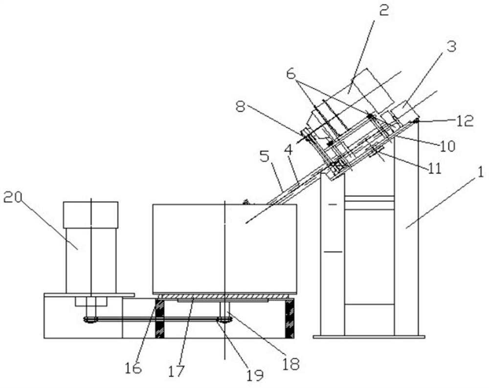
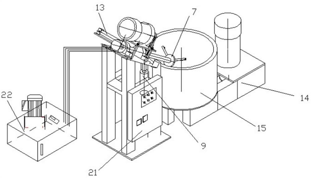
[0050] A wheel hub polishing machine, including a frame 1, a horizontal straight-side motor 2, a hollow rotary cylinder 3, a cylinder connecting rod 4, a rotating main shaft 5, a vertical bearing 6, a three-jaw chuck 7, a sprocket combination A 8, and a lift Oil cylinder 9, lifting plate 10, positioning pin 11, rotating plate 12, cylinder 13, seat frame 14, vertical drum 15, drum supporting plate 16, flange bearing plate 17, drum bottom shaft 18, sprocket combination B 19 , vertical motor 20, control cabinet 21, hydraulic station 22,

[0051] Frame 1 is an integrated structure made of square tube welding with length*width*height 900MM*700MM*2100MM.

[0052] The horizontal direct-connected motor 2 is composed of a forward and reverse motor and a gearbox group, and is fixed on the rotating plate 12 after being tensioned by a chain.

[0053] The hollow rotary oil cylinder 3 is an existing technology, and the hydraulic station 22 provides a driving force, and the internal piston ...

Embodiment 2

[0077] A wheel hub polishing machine, including a frame 1, a horizontal straight-side motor 2, a hollow rotary cylinder 3, a cylinder connecting rod 4, a rotating main shaft 5, a vertical bearing 6, a three-jaw chuck 7, a sprocket combination A 8, and a lift Oil cylinder 9, lifting plate 10, positioning pin 11, rotating plate 12, cylinder 13, seat frame 14, vertical drum 15, drum supporting plate 16, flange bearing plate 17, drum bottom shaft 18, sprocket combination B 19 , vertical motor 20, control cabinet 21, hydraulic station 22,

[0078] Frame 1 is an integrated structure made of square tube welding with length*width*height 900MM*700MM*2100MM.

[0079] The horizontal direct-connected motor 2 is composed of a forward and reverse motor and a gearbox group, and is fixed on the rotating plate 12 after being tensioned by a chain.

[0080] The hollow rotary oil cylinder 3 is an existing technology, and the hydraulic station 22 provides a driving force, and the internal piston ...

Embodiment 3

[0104] The present invention also relates to a method for using a hub polishing machine, comprising the following steps:

[0105] A: Turn on the power supply of the control cabinet 21 and compress the air;

[0106] B: The control cabinet 21 panel starts the hydraulic station 22 to raise the lifting cylinder 9 to the highest point, and at the same time ejects the cylinder 13 so that the three-jaw chuck 7 is outside the vertical drum 15, then lowers the lifting cylinder 9 to the bottom point, and passes The hollow rotary cylinder 3 opens the three-jaw chuck 7 to clamp and fix the hub;

[0107] C: Lift the lifting cylinder 9 to the highest point, return the cylinder 13, and lower the lifting cylinder 9 into the vertical drum;

[0108] D: Start the horizontal direct-connected motor 2 and the vertical motor 20;

[0109] E: According to the original set speed and time, stop running after reaching the set value;

[0110] F: Reverse operation to take out the wheel hub, the control ...


PUM

PropertyMeasurementUnit
pore sizeaaaaaaaaaa

Abstract

The invention belongs to the technical field of mechanical equipment, and relates to a hub polishing machine. The hub polishing machine comprises a rack, a horizontal straight-edge motor, a hollow rotary oil cylinder, an oil cylinder connecting rod, a rotating main shaft, a vertical bearing, a three-jaw chuck, a chain wheel combination A, a lifting oil cylinder, a lifting plate, a positioning pin, a rotating plate, an air cylinder, a seat frame, a vertical rotary drum, a rotary drum supporting plate, a flange bearing disc, a roller bottom shaft, a chain wheel combination B, a vertical motor, a control cabinet and a hydraulic station. The invention further relates to a using method of the hub polishing machine. According to the hub polishing machine, mechanical equipment is easy to operate, and one person can replace the original one-line cleaning process; products are consistent in smoothness after being polished for a fixed time, and the production and qualification rate is improved; the middle carrying process and potential safety hazards are reduced by placing in the subsequent procedure of a numerical control machine tool; and environmental pollution is improved through regular water change and reasonable discharge.

Description

technical field [0001] The invention belongs to the technical field of mechanical equipment, and in particular relates to a hub polishing machine and a using method thereof. Background technique [0002] The general production process of aluminum alloy wheels is melting - low pressure casting - heat treatment - shot blasting - cleaning - X-ray inspection - drilling - machining - painting cleaning - packaging. [0003] There are disadvantages in the existing process: 1. At present, most factories have increased the painting and cleaning process, which is inefficient and takes a long time; 2. The wheel hub needs to be transported from the machining workshop to the painting workshop, and there are various safety hazards in the transportation process; 3. Inconsistency in the cleaning process requires rework, and the pass rate is low; 4. After cleaning, there are errors in the recognition of the finish by human eyes, which increases labor costs. [0004] There is a technical sol...

Claims


Application Information

Patent Timeline
Patent Type & Authority Applications(China)
IPC IPC(8): B24B29/04B24B41/06B24B41/02B24B41/00B24B1/00
CPCB24B29/04B24B41/06B24B41/02B24B41/00B24B1/00
Inventor 刘灵俊庄黎军史朝辉
Owner DARE WHEEL MFG
Learn More