Cable-stayed rigid truss special equipment system
A technology of cable-stayed rigid truss and special equipment, applied in cable-stayed bridges, erecting/assembling bridges, bridge parts, etc., can solve the problem of low bearing capacity of Bailey sheet steel truss bridges, restricting the passage of heavy vehicles in marching, and not being too heavy Vehicles and other problems to achieve the effect of facilitating self-recovery, increasing interaction, and enhancing passability
- Summary
- Abstract
- Description
- Claims
- Application Information
AI Technical Summary
Problems solved by technology
Method used
Image
Examples
Embodiment 1
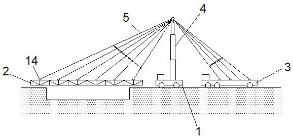
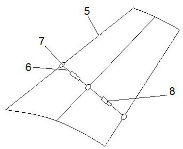
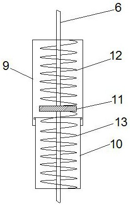
[0045] Such as Figure 1-5 As shown, a cable-stayed rigid truss special equipment system; including a steel truss 2, a first vehicle 1; the first vehicle 1 is loaded with a support rod 4, and the support rod 4 is a telescopic rod, and the support rod 4 The top is provided with a fixing piece 14, one side of the fixing piece 14 is connected with a plurality of tie rods 5, and the other ends of the plurality of tie rods 5 are all connected with the steel truss 2, and the plurality of tie rods 5 are uniformly arranged along the steel truss 2 Horizontally distributed, the rigid truss is erected on both sides of the river or ditch; the other side of the top fixing part 14 of the support rod 4 is connected to a plurality of tie rods 5, and the other ends of the plurality of tie rods 5 are connected to the second vehicle 3, the second vehicle 3 is a counterweight vehicle; ropes 6 are connected between the plurality of pull rods 5, and buffer members 8 are arranged on the ropes 6.
...
Embodiment 2
[0052] Such as Figure 6-7 As shown, the support rod 4 is a "gate" structure, and the support rod 4 of the "gate" structure has two support rods 4, which form two sets of cable-stayed structures, and pull the steel truss 2 at the same time on both sides of the steel truss 2 , to increase the stability; the support rod 4 is a "human" structure, and the support rod 4 is set in a "human" structure, and is fixed at the center of the steel truss 2 through the tie rod 5.
Embodiment 3
[0054] On the basis of Embodiment 1, in order to make the tie rod 5 play a better tension effect, increase the interaction between the steel truss 2 and the tie rod 5, so that the steel truss 2 can play a better supporting role, increase the load capacity, increase Stability, the distance between two adjacent tie rods 5 on the steel truss 2 is D, the angle formed by the tie rods 5 and the support rod 4 is θ, the range of θ is 45-90°, the height of the support rod 4 is H, two adjacent The length of the tie rod 5 close to the support rod 4 is L1, and the length of the tie rod 5 away from the support rod 4 is L2, then D satisfies the following relationship:
[0055] D=φ sinθ(L2-L1)H;
[0056] Among them, the unit of D, H, L1 and L2 is m; φ is an adjustment constant, and the value range is 0.8-2.36.
[0057] Dn-D n-1 =β·1 / 2n; In the above formula: Dn-D n-1 is the distance between the nth tie rod 5 and the n-1th tie rod 5 on the steel truss 2, in m; β is the relationship coeffic...
PUM
 Abstract
Description
Claims
Application Information
 - R&D
- Intellectual Property
- Life Sciences
- Materials
- Tech Scout
- Unparalleled Data Quality
- Higher Quality Content
- 60% Fewer Hallucinations
Browse by: Latest US Patents, China's latest patents, Technical Efficacy Thesaurus, Application Domain, Technology Topic, Popular Technical Reports.
© 2025 PatSnap. All rights reserved.Legal|Privacy policy|Modern Slavery Act Transparency Statement|Sitemap|About US| Contact US: help@patsnap.com


