Self-acceleration locking phase-locked loop

A phase-locked loop and self-acceleration technology, applied in the automatic control of power, electrical components, etc., can solve the problems of affecting the frequency locking effect, restoring the locking frequency, and relying on digital auxiliary technology, so as to reduce the design cost and take into account the speed and phase Effects of noise and shortened lock time

Active Publication Date: 2022-01-04
江苏稻源科技集团有限公司
View PDF12 Cites 0 Cited by
  • Summary
  • Abstract
  • Description
  • Claims
  • Application Information

AI Technical Summary

Problems solved by technology

In many application scenarios, the frequency required by integrated circuits is not single, and frequency hopping may be required according to needs. How to quickly lock after frequency hopping brings challenges to PLL design
Some circuits have complex application scenarios, and external interference will affect the frequency locking effect, causing the phase-locked loop to lose lock. Under the action of negative feedback adjustment, how to restore the locked frequency is also a difficult problem
[0003] In the prior art, there are methods that add more charging branches in the charge pump, which will cause additional power consumption and noise; there are methods that rely on digital assistance technology, and this method will cause more serious noise problems

Method used


Image

  • Self-acceleration locking phase-locked loop
  • Self-acceleration locking phase-locked loop
  • Self-acceleration locking phase-locked loop

Examples


Embodiment Construction

[0022] The present invention will be further explained below in conjunction with the accompanying drawings.

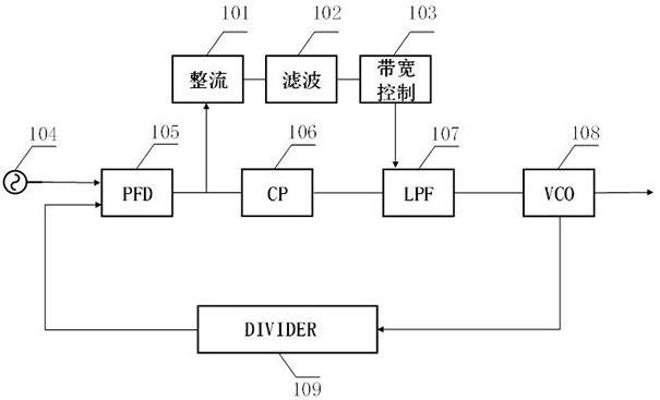
[0023] like figure 1 As shown in the figure, a self-accelerating phase-locked loop includes a traditional analog phase-locked loop part and an auxiliary circuit. It consists of a frequency discriminator (LPF) 107, a voltage controlled oscillator (VOC) 108, and a frequency divider (DIVIDER) 109. The frequency discriminator 105, the charge pump 106, the low-pass filter 107, and the voltage controlled oscillator 108 are connected in sequence, and the voltage The output end of the controlled oscillator 108 is fed back to one input end of the frequency and phase detector 105 through the frequency divider 109 , the other input end of the frequency and phase detector 105 is connected to the reference frequency source 104 , and the output end of the voltage controlled oscillator 108 as the output of the phase-locked loop.

[0024] The auxiliary circuit includes a rectifier 1...


PUM


Abstract

The invention discloses a self-acceleration locking phase-locked loop, and the phase-locked loop comprises a phase frequency detector, a charge pump, a low-pass filter, a voltage-controlled oscillator, a frequency divider, a rectifier, a filter and a bandwidth control circuit. The phase frequency detector, the charge pump, the low-pass filter and the voltage-controlled oscillator are sequentially connected; the output of the voltage-controlled oscillator is fed back to one input end of the phase frequency detector through the frequency divider, and the other input end of the phase frequency detector is connected with the reference frequency source. The output end of the phase frequency detector is further connected with the input end of the rectifier, the rectifier, the filter and the bandwidth control circuit are sequentially connected, and the bandwidth control circuit is used for generating a control word signal in proportional relation with an output signal of the phase frequency detector and inputting the control word signal to the low-pass filter; the bandwidth is controlled by controlling the access number of capacitors in the parallel capacitor array of the low-pass filter, so that the phase-locked loop accelerates to lock the reference frequency.

Description

technical field [0001] The invention relates to a phase-locked loop structure. Background technique [0002] With the continuous improvement of the performance of integrated circuits, the frequency of the chip is also gradually increasing, but due to the limitation of printed circuit board technology, it becomes more and more difficult to provide a higher frequency clock signal to the chip externally. Therefore, inside the chip, It is very important to generate a stable clock. Phase-locked loops (PLL) is a frequency and phase synchronization technology realized by feedback control principle. Its function is to synchronize the clock output by the circuit with its external reference clock. When the frequency or phase of the reference clock changes, the phase-locked loop detects the change and adjusts the output frequency through its internal feedback system until the two are resynchronized, also known as "phase-locked". In many application scenarios, the frequency required b...

Claims


Application Information

Patent Timeline
Patent Type & Authority Applications(China)
IPC IPC(8): H03L7/08H03L7/087H03L7/099
CPCH03L7/08H03L7/087H03L7/099
Inventor 杨逸凡王彬徐凯张永生赵佳佳程晨
Owner 江苏稻源科技集团有限公司
Why Eureka
Try Eureka