Supercharge Your Innovation With Domain-Expert AI Agents!

Blast furnace slag flushing device and method

A blast furnace slag flushing and water slag technology, applied in the field of blast furnace smelting, can solve the problems of affecting the filtering effect, corroded cover plate, heavy workload, etc., and achieve the effect of prolonging the service life, avoiding corrosion, and reducing the number of maintenance

Active Publication Date: 2022-01-07
鞍钢集团工程技术有限公司
View PDF8 Cites 0 Cited by
  • Summary
  • Abstract
  • Description
  • Claims
  • Application Information

AI Technical Summary

Problems solved by technology

There are some disadvantages in the traditional bottom filtration method, including: 1) The installation position of the granulation device needs to maintain a certain height difference from the end of the red slag ditch, and there are limitations in the selection of sites during new construction and renovation
2) There are gaps in the cover plate above the water slag ditch, water vapor is scattered around, and the cover plate is corroded
3) The filter tube in the filter tank is in direct contact with the pebbles, and has a short lifespan, so it needs to be replaced in time. Once replaced, the pebble layer needs to be emptied, and the workload is huge
The pores of the filter tube are easily blocked in turbid filtered water. Backwashing is only useful in the early stage. As the number of blocked pores increases, the filtering effect will be seriously affected.

Method used


Image

  • Blast furnace slag flushing device and method
  • Blast furnace slag flushing device and method
  • Blast furnace slag flushing device and method

Examples


Embodiment Construction

[0038] The present invention will be described in detail below in conjunction with the accompanying drawings, but it should be pointed out that the implementation of the present invention is not limited to the following embodiments.

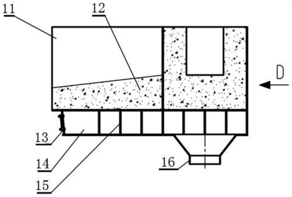
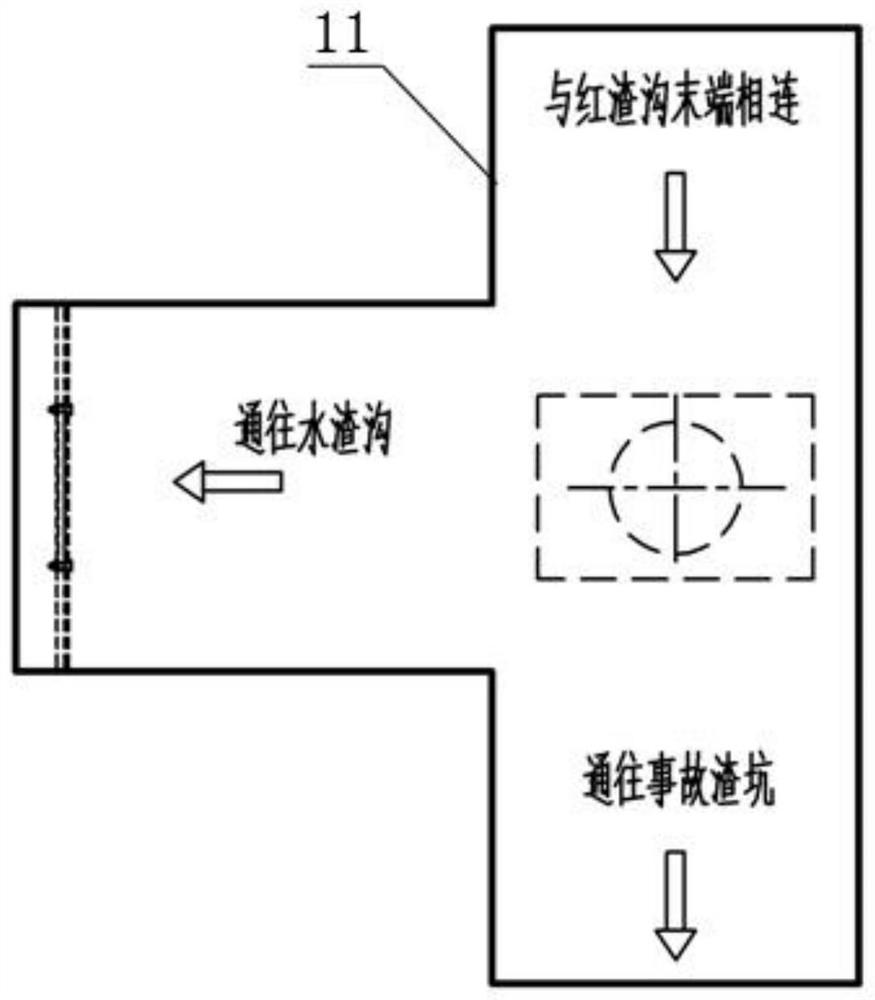
[0039] See Figure 1-Figure 15 , a blast furnace slag flushing device, including a granulatable slag ditch nozzle 1, a water slag ditch cover plate 2, and a filter pool 3. The granulizable slag ditch nozzle 1 is installed at the end of the red slag ditch. The overall hoisting of the slag ditch flow nozzle 1 is convenient and quick. The granulatable slag ditch nozzle 1 includes a steel channel 11, a water tank 14, and a porous granulation plate 13. The channel in the steel channel 11 is formed by refractory bricks or castables 12 to resist red slag erosion and heat insulation; the bottom of the steel channel 11 A water tank 14 with a cooling effect is fixed, the plane of the water tank 14 matches the bottom plane of the steel tank 11, the end of ...


PUM


Abstract

The invention relates to a blast furnace slag flushing device and method. The blast furnace slag flushing device comprises a pelletizable slag runner flow nozzle, a water slag runner cover plate and a filtering pond, wherein the pelletizable slag runner flow nozzle is installed at the tail end of a red slag runner and comprises a steel tank and a water tank, a channel is formed in the steel tank through refractory bricks or castable, the water tank is fixed to the bottom of the steel tank, the tail end of the water tank is connected with a porous granulating plate, the water slag runner cover plate is laid on the whole water water slag runner and comprises a first cover plate body and a second cover plate body, the first cover plate body and the second cover plate body are connected in a staggered mode and meshed with each other through teeth, the filtering pond is arranged at the tail end of the water slag runner, concrete pits which are staggered transversely and longitudinally are arranged at the bottom of the filtering pond, filter pipelines are arranged in the pits, the upper surfaces of the pits are blocked by perforated strainers, so that the bottoms of the pits are kept in a plane, and then 3-4 layers of cobblestones with different granularities are paved. The blast furnace slag flushing device has the advantages that the problem that a traditional granulator is limited by a site is solved, the blast furnace slag flushing device is compact in structure, convenient to disassemble and overhaul and better in granulation effect, and the cooling rate is increased.

Description

technical field [0001] The invention belongs to the technical field of blast furnace smelting, and in particular relates to a blast furnace slag flushing device and method. Background technique [0002] In blast furnace production, liquid blast furnace red slag needs to be water-quenched and granulated into granular water slag, which is transported and sold as a by-product of blast furnace production. The bottom filtration method is one of the more common blast furnace slag flushing methods. The blast furnace red slag entering the slag flushing ditch is water-quenched under the action of high-pressure water sprayed from the porous granulation nozzle. The water slag after water quenching enters the filter tank through the water slag ditch for dehydration, and the dehydrated water slag is lifted out of the slag field by the grab crane. There are some disadvantages in the traditional bottom filtration method, including: 1) The installation position of the granulation device ne...

Claims


Application Information

Patent Timeline
IPC IPC(8): C21B3/08
CPCC21B3/08C21B2400/024C21B2400/04C21B2400/05Y02W30/50
Inventor 李世明战奇张超马海林赵波张维巍李霞范丽丽
Owner 鞍钢集团工程技术有限公司
Features
  • R&D
  • Intellectual Property
  • Life Sciences
  • Materials
  • Tech Scout
  • Unparalleled Data Quality
  • Higher Quality Content
  • 60% Fewer Hallucinations
Learn More