Environment-friendly aluminum product melting and recycling equipment

A recycling equipment, aluminum technology, applied in the direction of lighting and heating equipment, charging treatment types, chemical instruments and methods, etc., can solve the problems of inconvenient height adjustment, exhaust gas cannot be filtered well, and sputtering is easy to occur, etc. Achieve the effect of improving integrity, reducing waste and improving cleaning effect

Pending Publication Date: 2022-01-07
陈来金
View PDF7 Cites 0 Cited by
  • Summary
  • Abstract
  • Description
  • Claims
  • Application Information

AI Technical Summary

Problems solved by technology

[0005] In order to overcome the inconvenience of adjusting the height, it is easy to produce sputtering when pouring the smelted metal liquid, and at the same time, the generated waste gas cannot be filtered well. The technical problem is to provide a method that can adjust the height of the melting furnace according to needs. At the same time, it is an environmentally friendly aluminum melting recycling equipment that can filter the waste gas generated during the melting process

Method used


Image

  • Environment-friendly aluminum product melting and recycling equipment
  • Environment-friendly aluminum product melting and recycling equipment
  • Environment-friendly aluminum product melting and recycling equipment

Examples


Embodiment 1

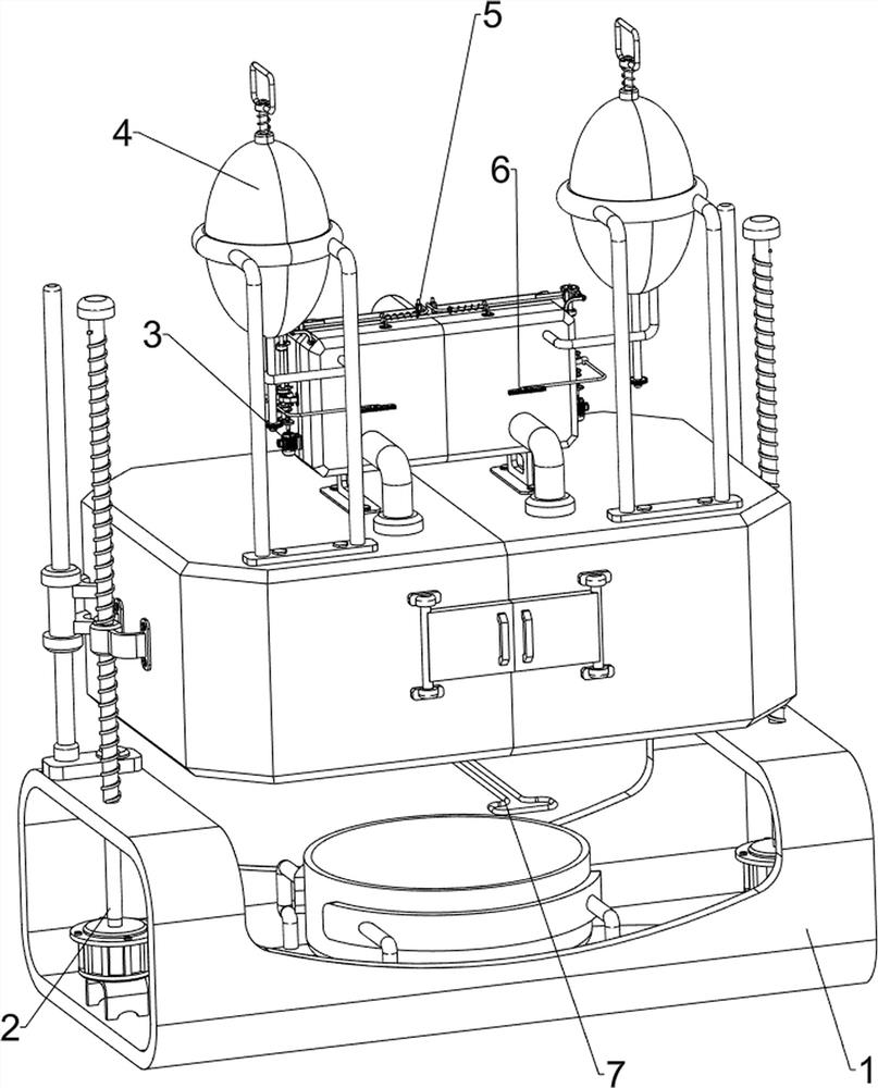
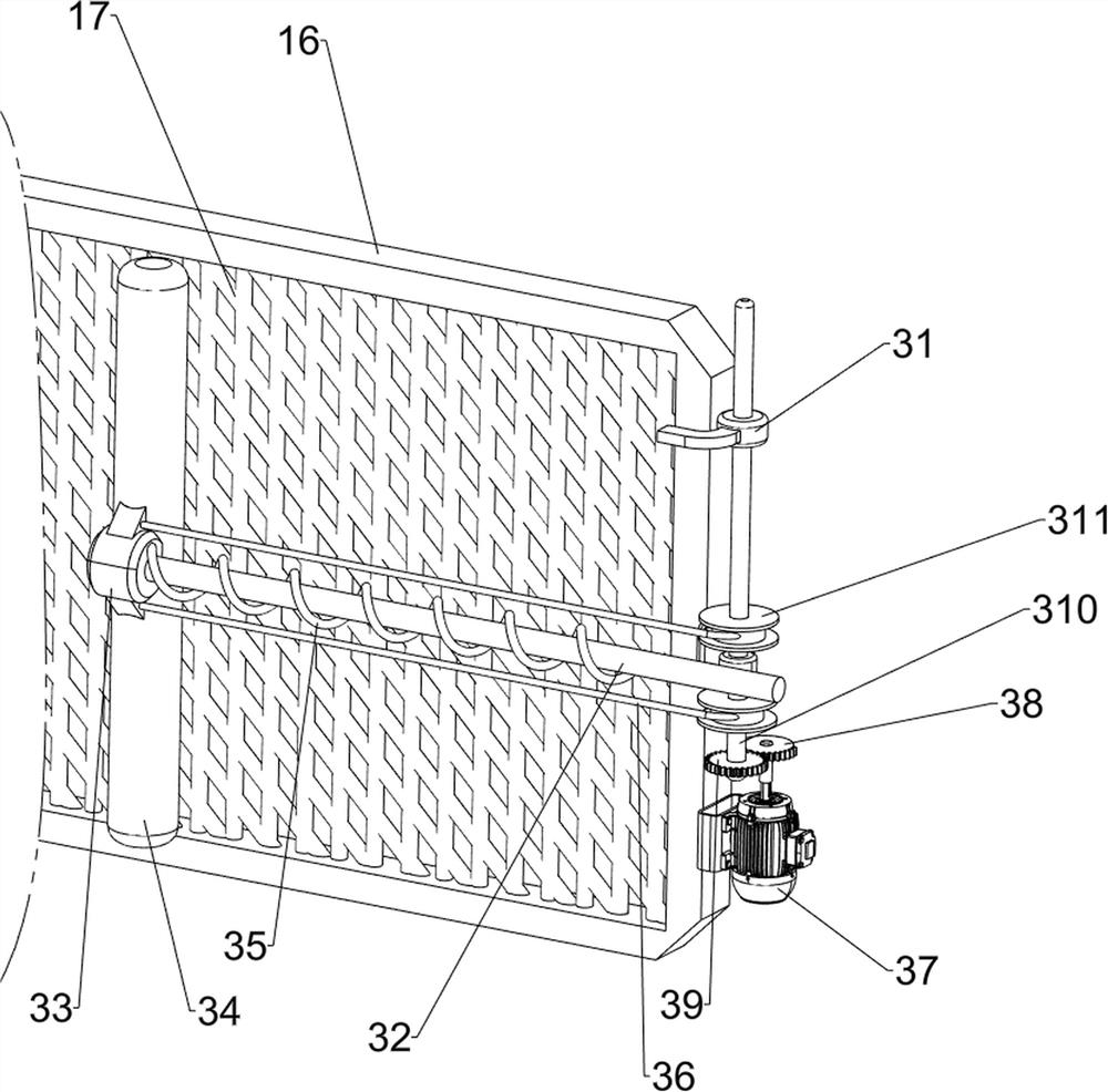
[0088] A kind of aluminum melting recovery equipment for environmental protection, such as figure 1 with figure 2 As shown, it includes a base 1, a collection tray 11, a melting furnace 12, a discharge tray 13, a rising guide rail 14, an exhaust pipe 15, a cleaning box 16, a cleaning filter screen 17, an air suction fan 18, a lifting mechanism 2, and a cleaning mechanism 3 and the water outlet mechanism 4, a collection tray 11 is placed in the middle of the base 1, rising guide rails 14 are symmetrically arranged on the left and right sides of the upper part of the base 1, and a melting furnace 12 is slidingly provided between the two rising guide rails 14, and a melting furnace 12 is provided with a storage tank. Feeding tray 13, two exhaust pipes 15 are provided through the front side of the top of the melting furnace 12, and a cleaning box 16 is provided in the middle of the top of the melting furnace 12. The front side of the cleaning box 16 is connected to the two exhaus...

Embodiment 2

[0091] In a preferred embodiment of the present invention, as Figure 2-Figure 4 As shown, the lifting mechanism 2 includes a first bracket 21, a first motor 22, a first rotating shaft 23, a screw mandrel 24 and a first connecting block 25, and the left and right sides of the bottom of the base 1 are provided with a first bracket 21, two second A first motor 22 is installed on a support 21, and the left and right sides of the top of the base 1 are rotatably provided with a first rotating shaft 23. 23 tops are connected with screw mandrels 24, and the middle part of the left and right sides of the melting furnace 12 is provided with a first connecting block 25, and the two first connecting blocks 25 are all threadedly connected with the screw mandrel 24 on the same side.

[0092] When the worker needs to adjust the melting furnace 12 to a proper position, the worker can start the first motor 22, and the rotation of the output shaft of the first motor 22 will drive the first rot...

Embodiment 3

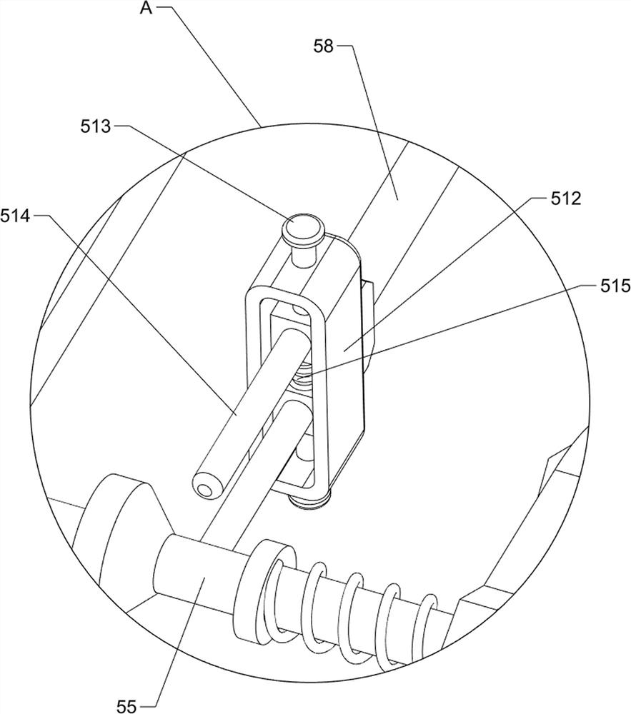
[0098] In a preferred embodiment of the present invention, as Figure 5-Figure 8As shown, a self-locking rebound mechanism 5 is also included, and the self-locking rebound mechanism 5 includes a fourth bracket 51, a fifth bracket 52, a ratchet gear 53, a wedge block 54, a third slide bar 55, a third spring 56, Extrusion block 57, first connecting rod 58, fourth spring 59, third connecting block 510, first extruding rod 511, fourth connecting block 512, fourth sliding rod 513, second extruding rod 514 and fifth Spring 515, the cleaning box 16 front sides are provided with the 4th support 51 at intervals, the quantity of the 4th support 51 is two, the 5th support 52 is all provided with the left and right sides of cleaning box 16 tops, all slides on the 5th support 52 of two The formula is provided with a third sliding rod 55, and the front sides of the two third sliding rods 55 are all sleeved with a third spring 56, and the two ends of the third spring 56 are respectively conn...


PUM


Abstract

The invention relates to recycling equipment, in particular to environment-friendly aluminum product melting and recycling equipment. The invention provides the environment-friendly aluminum product melting and recycling equipment that the height of a melting furnace can be adjusted according to needs, and meanwhile, waste gas generated in the melting process can be filtered. The invention provides the environment-friendly aluminum product melting and recycling equipment which comprises a base, a collecting disc, ascending guide rails, the melting furnace, a material placing disc, air exhaust pipes, a cleaning box and a cleaning filter screen, wherein the collecting disc is placed at the middle of the base, the ascending guide rails are symmetrically arranged at the upper part of the base, the melting furnace is arranged between the two ascending guide rails in a sliding manner, the material placing disc is arranged in the melting furnace, the two air exhaust pipes are arranged at the top of the melting furnace in a penetrating manner, the cleaning box is arranged at the middle of the top of the melting furnace, and the cleaning filter screen is arranged in the cleaning box. According to the environment-friendly aluminum product melting and recycling equipment, lifting mechanisms are arranged, the lifting mechanisms are matched with the melting furnace and can adjust the position of the melting furnace, and then a worker can conduct melting treatment conveniently.

Description

technical field [0001] The invention relates to a recycling device, in particular to an aluminum melting recycling device for environmental protection. Background technique [0002] In the current life, waste aluminum products will continue to be produced, so people usually recycle waste aluminum products for smelting and reprocessing, and in the process of melting aluminum products, some toxic substances will be produced, and these substances will be harmful to the human body when they diffuse in the air. Therefore, when people melt and recycle aluminum products, they need to use aluminum product smelting and recycling equipment. However, most of the existing smelting and recycling equipment is inconvenient to adjust the height, and it is easy to produce sputtering when pouring the smelted metal liquid. , At the same time, the exhaust gas cannot be filtered well. [0003] Patent application number CN209024614U discloses a recycling and processing device for waste aluminum ...

Claims


Application Information

Patent Timeline
IPC IPC(8): F27B14/00F27B14/08F27D17/00F27D25/00B01D46/10B01D46/00F27B14/18
CPCF27B14/00F27B14/08F27D17/008F27D25/008B01D46/10F27B14/0806F27B2014/0818F27M2001/012F27M2003/13Y02P10/25Y02P10/20
Inventor 陈来金
Owner 陈来金
Why Eureka
Try Eureka