
Internal grouping type yarn winding water-blocking system of high-density optical cable

A technology of inner grouping and yarn winding, applied in the directions of light guides, optics, optical components, etc., can solve the problems of being unsuitable for multiple sets of casings to be used at the same time, interfering with the walking paths of each set of casings, and not having pitch adjustment. Pipe identification and management capabilities, small footprint, and the effect of improving production efficiency

Active Publication Date: 2022-01-07
YANGTZE OPTICAL FIBRE & CABLE CO LTD
View PDF8 Cites 0 Cited by
  • Summary
  • Abstract
  • Description
  • Claims
  • Application Information

AI Technical Summary

Problems solved by technology

At present, the yarn winding equipment on the market is either directly dragged and dropped without pitch adjustment, or is a very clumsy and bulky large-scale yarn binding machine that can adjust the pitch, covering an area of ​​1m. 2 -1.5m 2 , volume up to 2m 3 -3m 3 , and the weight is generally more than 1000kg. These yarn binding machines with adjustable pitch have relatively high binding tension. During production, the optical fibers in the micro-cluster tubes often appear to be strangled, resulting in increased fiber attenuation.
[0007] At the same time, for the production of high-density micro-cluster optical cables with large cores, in order to improve production efficiency, it is often necessary to group many casings and wind them at the same time to identify them and form cables or sheaths together. If the size of the winding equipment is too large, it will interfere with the running of each group of casings. The path requires a lot of space for equipment placement. In addition, the existing binding machines that can adjust the pitch weigh more than a ton. It requires a forklift to move, which is extremely unsuitable for multiple sets of casings. use simultaneously

Method used


Image

  • Internal grouping type yarn winding water-blocking system of high-density optical cable
  • Internal grouping type yarn winding water-blocking system of high-density optical cable

Examples


Embodiment Construction

[0029] In order to make the object, technical solution and advantages of the present invention clearer, the present invention will be further described in detail below in conjunction with the accompanying drawings and embodiments. It should be understood that the specific embodiments described here are only used to explain the present invention, not to limit the present invention. In addition, the technical features involved in the various embodiments of the present invention described below can be combined with each other as long as they do not constitute a conflict with each other.

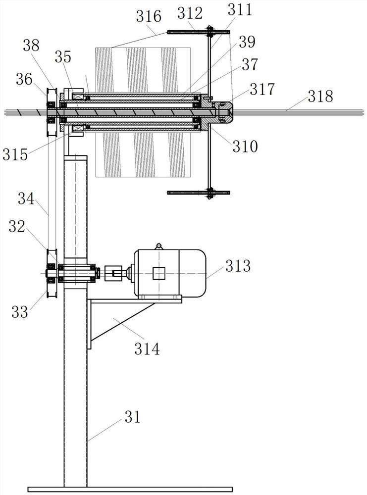
[0030] refer to figure 1 , figure 2 , an inner grouped yarn-winding water-blocking system for high-density optical cables, including a stranding table 100 and a sleeve winding unit, wherein:

[0031]The sleeve winding unit includes a pay-off head matrix 400, a yarn winding machine 300 and a guide wheel 200, and the pay-off head matrix 400 has a plurality of sleeve winding reels, so that the s...


PUM


Abstract

The invention discloses an internal grouping type winding water-blocking system for a high-density optical cable, wherein the system comprises a twisting table and a casing pipe yarn winding unit; the casing pipe yarn winding unit comprises a pay-off head matrix, a yarn winding machine and a guide wheel, and the pay-off head matrix is provided with a plurality of casing pipe wire spools; the yarn winding machine comprises a machine frame, a motor, a main fixed shaft barrel, a flying shuttle rotating barrel, a movable ring mold base, a yarn ball rotating barrel, a flying shuttle and a yarn guide pipe; the flying shuttle rotating barrel is mounted on the inner side of the main fixed shaft barrel through a first bearing, a rotating shaft of the motor is connected with the first end of the flying shuttle rotating barrel, and the movable ring mold base is mounted at the second end of the flying shuttle rotating barrel; and the yarn ball rotating barrel is mounted on the outer side of the main fixed shaft barrel through a second bearing, the flying shuttle is mounted on the movable ring mold base, the yarn guide pipe is mounted on the flying shuttle, and the guide wheel is mounted on a supporting frame. According to the invention, a grouping type winding mode is adopted, and physical yarn winding isolation is completed on grouped casing pipe groups, so that identification is facilitated; and a casing pipe is woven by water-blocking yarns in a winding mode, isolation and water blocking are achieved, tension is small, optical fibers in the casing pipe cannot be damaged, and use is quite reliable.

Description

technical field [0001] The invention belongs to the field of optical cable manufacturing equipment, and more specifically relates to an inner-group winding water blocking system for high-density optical cables. Background technique [0002] With the rise of the Internet cloud and data centers, a large number of high-density optical fiber dry-type optical cables are widely used, because of a series of advantages such as large data transmission, small structural diameter, small bending radius, and friendly construction conditions, they are more and more popular in the market. Many customers choose. [0003] In order to save scarce tube hole resources, large-core high-density micro-cluster optical cables are becoming more and more popular. As the number of optical fiber cores in products continues to increase, there are more and more optical fiber sleeve units in the optical cable structure, such as Among the optical cables used on the Hong Kong-Zhuhai-Macao Bridge, the number...

Claims


Application Information

Patent Timeline
IPC IPC(8): G02B6/44
CPCG02B6/4486G02B6/449G02B6/44384
Inventor 黄杰李智刚阮云芳刘爱华祁林
Owner YANGTZE OPTICAL FIBRE & CABLE CO LTD
Learn More