Limiting type conveying device for food packaging bags

A conveying device and packaging bag technology, which is applied to conveyors, conveyor objects, transportation and packaging, etc., can solve the problem of easy slipping of packaging bags, and achieve the effects of improving loading efficiency, preventing slippage and increasing contact area.

Active Publication Date: 2022-01-11
四川远方云天食品科技有限公司
View PDF13 Cites 3 Cited by
  • Summary
  • Abstract
  • Description
  • Claims
  • Application Information

AI Technical Summary

Problems solved by technology

[0003] The purpose of the present invention is to overcome the deficiencies of the prior art and provide a limited conveying device for food pac

Method used


Image

  • Limiting type conveying device for food packaging bags
  • Limiting type conveying device for food packaging bags
  • Limiting type conveying device for food packaging bags

Examples


Embodiment 1

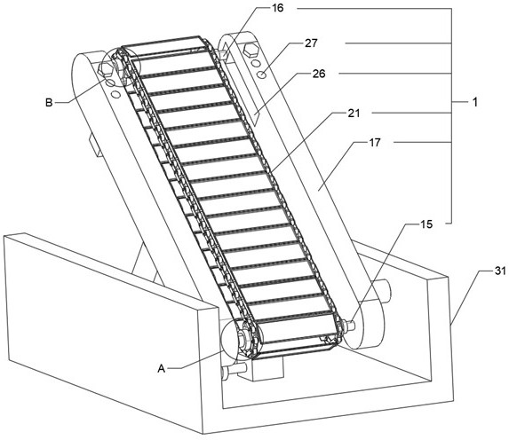
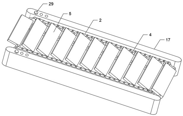
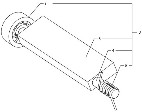
[0030] Embodiment one, as Figure 1 to Figure 4As shown, a position-limiting conveying device for food packaging bags includes a chain conveying mechanism 1 arranged obliquely. The chain conveying mechanism 1 includes two sets of chain transmission mechanisms 2 arranged in parallel. There are a number of rotating support devices 3, which are evenly arranged along the transmission direction of the chain transmission mechanism 2. The rotating support device 3 includes a support shaft 4 and a support plate 5. One end of the support shaft 4 is connected to one of the chains through a torsion spring 6. The transmission mechanism 2 is connected, and the other end of the support shaft 4 is connected with another chain transmission mechanism 2 through the limit rotating member 7. The support plate 5 is fixedly sleeved on the support shaft 4, and the transmission direction of the support plate 5 and the chain transmission mechanism 2 is in the direction of Set at an acute angle (that i...

Embodiment 2

[0032] Embodiment two, such as figure 1 , figure 2 , Figure 7 and Figure 8 As shown, the chain transmission mechanism 2 includes a driving sprocket 19 and a driven sprocket 20 arranged in rotation, and the driven sprocket 20 is connected to the driving sprocket 19 through an endless chain 21. The chain transmission mechanism 1 also includes a driving shaft 15, Driven shaft 16 and two conveying plates 17, two conveying plates 17 are arranged in parallel, and driving shaft 15 and driven shaft 16 are all positioned between two conveying plates 17, and driving shaft 15 is rotationally connected with conveying plate 17, and driven shaft Both ends of 16 are rotatably connected with a sliding mechanism 18, the sliding mechanism 18 is slidingly connected with the conveying plate 17, the driving sprocket 19 is fixedly sleeved on the driving shaft 15, and the driven sprocket 20 is fixedly sleeved on the driven shaft 16 Above, the driving shaft 15 is connected to the driving mechan...

Embodiment 3

[0033] Embodiment three, as figure 1 and Figure 9 As shown, it also includes a movable bottom frame 31, and the chain conveying mechanism 1 is obliquely arranged on the movable bottom frame 31. The height of the input end of the chain conveying mechanism 1 is lower than the height of the output end, and the side wall of the conveying plate 17 passes through the pin shaft and moves The inner side walls of the bottom frame 31 are hinged, the bottoms of the two conveying plates 17 are connected by connecting rods 32, the moving bottom frame 31 is hinged with a cylinder 33, and the telescopic shaft of the cylinder 33 is hinged with the connecting rod 32; the bottom of the moving bottom frame 31 is provided with a ten thousand To the wheel, it is convenient to move the bottom frame 31 to drive the chain conveying mechanism to move. The inclination angle of the chain conveying mechanism 1 can be adjusted through the cylinder 33, which can adapt to various loading heights. At the sa...


PUM


Abstract

The invention discloses a limiting type conveying device for food packaging bags. The limiting type conveying device for the food packaging bags comprises an obliquely-arranged chain type conveying mechanism, the chain type conveying mechanism comprises two chain transmission mechanisms arranged in parallel, a plurality of rotary supporting devices are arranged between the two chain transmission mechanisms, the plurality of rotary supporting devices are evenly arranged in the conveying direction of the chain transmission mechanisms, each rotary supporting device comprises a supporting shaft and a supporting plate, one end of each supporting shaft is connected with one chain transmission mechanism through a torsional spring, the other end of each supporting shaft is connected with the other chain transmission mechanism through a limiting rotating piece, the supporting shafts are fixedly sleeved with the supporting plates, the supporting plates and the conveying direction of the chain transmission mechanisms form acute angles, and the limiting rotating piece is used for enabling the multiple supporting plates supporting the packaging bags to be rotationally connected into a supporting plane in the conveying direction of the chain transmission mechanisms and limiting sliding of the packaging bags through the supporting plates located below the packaging bags. The limiting type conveying device is used for solving the problem that the packaging bags are prone to slipping off due to the fact that an existing conveying device conveys the packaging bags from low to high.

Description

technical field [0001] The invention relates to the technical field of cargo transportation, in particular to a position-limiting conveying device for food packaging bags. Background technique [0002] The food transportation device plays an important role in the production of bagged food in every enterprise. The food transportation device has a strong transportation capacity and a long transportation distance. It can not only form a space transportation line, but also carry out vertical, horizontal and inclined assembly lines. Transportation, food transportation device greatly improves the efficiency of bagged food production, and also saves a lot of manpower and material resources, so it is widely used; the food processing process is roughly the transportation of food raw materials, raw material processing, food packaging and food packaging bags During the transportation of food raw materials, raw material packaging bags need to be loaded and transported. After the same fo...

Claims


Application Information

Patent Timeline
IPC IPC(8): B65G67/06B65G17/16B65G17/34B65G23/44B65G17/46B65G47/22B65G41/00
CPCB65G67/06B65G17/16B65G17/34B65G23/44B65G17/46B65G47/22B65G41/002B65G2201/0238
Inventor 柳鸷
Owner 四川远方云天食品科技有限公司
Why Eureka
Try Eureka