Structure and manufacturing method of miniature electric connector

A technology of an electrical connector and a manufacturing method, which is applied to the parts, connections, and fixed connections of the connecting device, can solve the problems of flux contamination, substrate cracking, metal fatigue, etc., and achieves improved on-current and reliability. , Improve stability and mechanical strength, improve assembly efficiency and effect

Pending Publication Date: 2022-01-11
XIAN MICROELECTRONICS TECH INST
View PDF21 Cites 0 Cited by
  • Summary
  • Abstract
  • Description
  • Claims
  • Application Information

AI Technical Summary

Problems solved by technology

[0002] The electrical interconnection between the early meter adding servo circuit and the quartz meter head was realized by hand-soldering insulated wires. Since the brazing process will generate thermal stress on known good circuits, there is a risk of substrate cracking and flux Contamination defects; in addition, interconnecting wires are not rigid connections, and are prone to displacement and metal fatigue under the action of external forces. These potential hidden dangers will directly affect the long-term reliability of the inertial navigation system
Due to the particularity of the circuit structure and high reliability requirements, there is currently no miniature electrical connector suitable for direct assembly inside the microcircuit on the market.

Method used


Image

  • Structure and manufacturing method of miniature electric connector
  • Structure and manufacturing method of miniature electric connector
  • Structure and manufacturing method of miniature electric connector

Examples


Embodiment Construction

[0023] In order to make the purpose, technical solutions and advantages of the embodiments of the present invention clearer, the technical solutions in the embodiments of the present invention will be clearly and completely described below in conjunction with the drawings in the embodiments of the present invention. Obviously, the described embodiments It is a part of embodiments of the present invention, but not all embodiments. The components of the embodiments of the invention generally described and illustrated in the figures herein may be arranged and designed in a variety of different configurations.

[0024] Accordingly, the following detailed description of the embodiments of the invention provided in the accompanying drawings is not intended to limit the scope of the claimed invention, but merely represents selected embodiments of the invention. Based on the embodiments of the present invention, all other embodiments obtained by persons of ordinary skill in the art wi...


PUM


Abstract

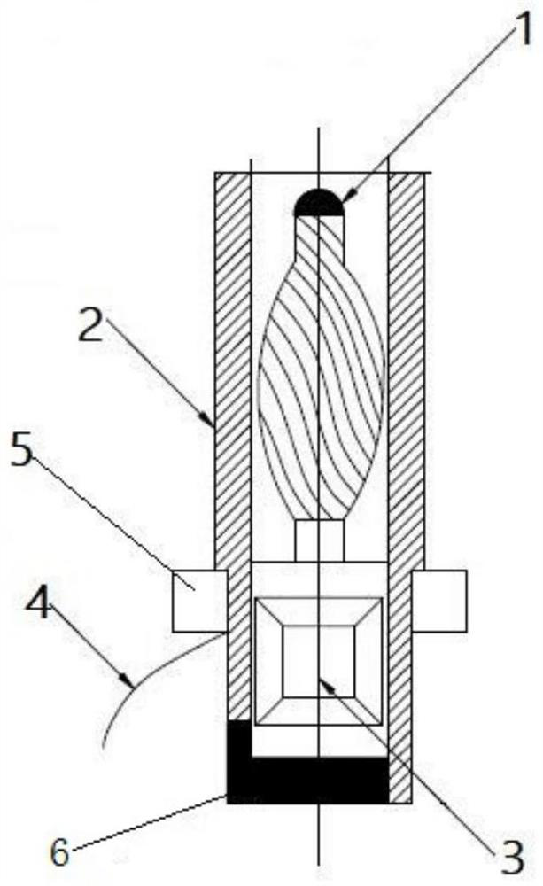
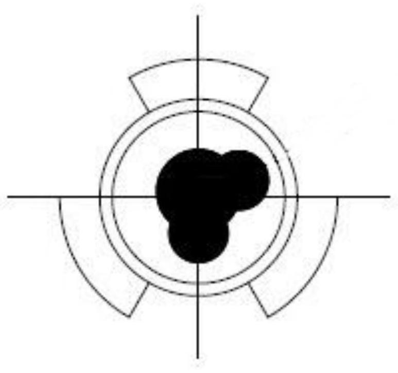
The invention discloses a structure and a manufacturing method of a miniature electric connector. The structure is characterized in that a pin assembly is located in an insulator; the insulation paste is located at one end of the insulator; the pin assembly comprises a twist pin, a crimping cylinder and an anaerobic copper wire; and the twist pin and the anaerobic copper wire are extruded, locked and fixedly connected through the crimping cylinder. According to the present invention, the twisted ends of a plurality of copper wires are welded to form the twist pin, and the other ends of the plurality of copper wires and one end of the anaerobic copper wire are locked and mutually conducted through the crimping cylinder; the pin assembly composed of the twist pin, the crimping cylinder and the anaerobic copper wire is placed in the insulator, and a flange sleeves the insulator. The miniature electric connector can be in butt joint with a quartz meter head, has the advantages of being small in size, detachable, small in resistance, resistant to high and low temperature, high in reliability and the like, and meanwhile meets various example test condition requirements of a hybrid integrated circuit.

Description

technical field [0001] The invention belongs to the field of electric interconnection of microelectronic devices, and relates to a structure and a manufacturing method of a micro electric connector. Background technique [0002] The electrical interconnection between the early meter adding servo circuit and the quartz meter head was realized by hand-soldering insulated wires. Since the brazing process will generate thermal stress on known good circuits, there is a risk of substrate cracking and flux In addition, the interconnection wire is not a rigid connection, and it is prone to displacement and metal fatigue under the action of external force. These potential hidden dangers will directly affect the long-term reliability of the inertial navigation system. Due to the particularity of the circuit structure and high reliability requirements, there is currently no miniature electrical connector suitable for direct assembly inside the microcircuit on the market. Contents of ...

Claims


Application Information

Patent Timeline
Patent Type & Authority Applications(China)
IPC IPC(8): H01R13/40H01R12/51H01R13/02H01R13/533H01R4/20H01R43/16H01R43/048H01R43/20
CPCH01R13/40H01R12/51H01R4/20H01R13/02H01R13/533H01R43/16H01R43/048H01R43/20
Inventor 任爱华李新玉周海张欲欣尚春亮
Owner XIAN MICROELECTRONICS TECH INST
Why Eureka
Try Eureka