
Board end connector assembly testing machine

A technology of board-side connector and testing machine, which is applied in the direction of electrical connection test, connection, and test of dielectric strength, etc., and can solve the problem of internal connection not in place, failure to use normally, failure of board-side connector assembly fit, conduction function inspection and other issues to achieve the effect of ensuring the yield rate and improving work efficiency

Active Publication Date: 2022-01-11
CHANGZHOU AMPHENOL FUYANG COMM EQUIP CO LTD
View PDF18 Cites 0 Cited by
  • Summary
  • Abstract
  • Description
  • Claims
  • Application Information

AI Technical Summary

Problems solved by technology

[0004] The technical problem to be solved by the present invention is: in order to overcome the fact that the automatic assembly equipment of the board end connector in the prior art cannot check the assembly fit, conduction function and other functions of the assembled board end connector, resulting in the failure of the internal connection during use If it is not in place and cannot be used normally, it provides a board terminal connector assembly testing machine

Method used


Image

  • Board end connector assembly testing machine
  • Board end connector assembly testing machine
  • Board end connector assembly testing machine

Examples


Embodiment Construction

[0046] The present invention will now be described in detail with reference to the accompanying drawings. These figures are schematic diagrams, which will be described only in a schematic manner, and therefore it only shows the configurations related to the present invention.

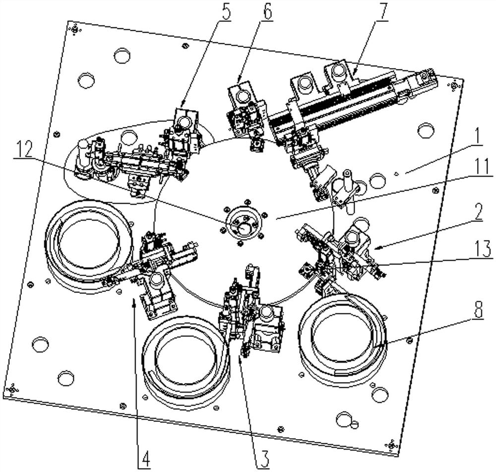
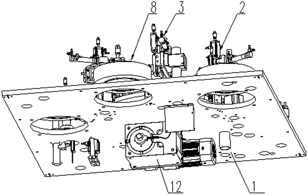
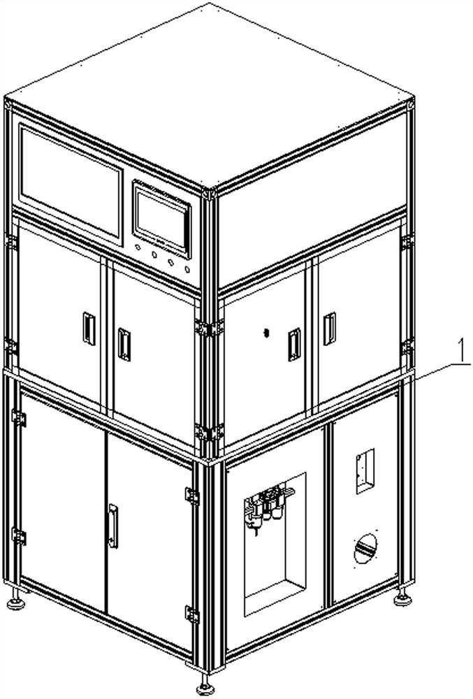
[0047] like figure 1 It is a schematic structural diagram of the present invention, a plate-end connector assembly test machine, including a base 1, rotatably mounted on the turntable 11 on the base 1, and the driving member 12 of the driving turntable 11 rotation, the output terminal of the drive member 12 and the turntable 11 Turn the connection, the driver 12 is the motor, figure 1 Middle equipment structure is installed image 3 Inside the box;

[0048] The upper casing mechanism 2, the upper insulating sheet mechanism 3, the upper pin mechanism 4, the highness test mechanism 5, the pressure test mechanism 6, and visual detection mechanism 7 are sequentially mounted along the rotating plate 11.

[0049] ...


PUM


Abstract

The invention relates to the technical field of connector production equipment, in particular to a board end connector assembly testing machine which comprises a base, a rotating disc rotationally installed on the base and a driving piece for driving the rotating disc to rotate, wherein the output end of the driving piece is rotationally connected with the rotating disc, and an upper shell mechanism, an upper insulating sheet mechanism, an upper contact pin mechanism, a height difference testing mechanism, a voltage withstanding testing mechanism and a visual inspection mechanism are sequentially installed on the base in the circumferential direction of the rotating disc. According to the invention, the automatic assembly of the board end connector is completed through the arrangement of the upper shell mechanism, the upper insulating sheet mechanism and the upper pin mechanism, through the arrangement of the height difference testing mechanism, the voltage withstanding testing mechanism and the visual detection mechanism, the height difference between the contact pin end part of the assembled board end connector and the end part of the shell on the side where the contact pin end part is located, the insulating property and the concentricity of the contact pin and the shell are detected respectively, and the testing procedure is directly performed after the assembling procedure is completed, so that the working efficiency is improved, and the yield of the output board end connector is ensured.

Description

Technical field [0001] The present invention relates to a technical field of production equipment connector, particularly to a board-side connector fitting tester. Background technique [0002] The electrical connector, in particular board-side connector based solder on the circuit board of electronic products, and the end of the supply line connector fitting, the wire end connector in communication with the board connector electrically, for electronic products to function properly. Typically this kind of board-side connector fitting comprises a housing, an insulating sheet and pins. [0003] Currently board connector assembly after assembly, the assembly may be due to the device is not assembled in place, so that the position of the plug connection is not tight enough, resulting in easier use during impact into ash, water and other normal use, and the composition is difficult to process for the connector conducting the test, enhanced efficiency, there is an existing board-side c...

Claims


Application Information

Patent Timeline
IPC IPC(8): H01R43/00H01R43/20G01B11/27G01R31/12G01R31/69
CPCH01R43/00H01R43/20G01R31/69G01R31/1227G01B11/27
Inventor 王鹏金
Owner CHANGZHOU AMPHENOL FUYANG COMM EQUIP CO LTD
Learn More