
Bus-intensive connector

A technology of connectors and busbars, applied in the field of electric power, can solve problems affecting construction, increasing cost, and accelerating oxidation speed, etc.

Active Publication Date: 2022-01-11
珠海光乐电力母线槽有限公司
View PDF10 Cites 0 Cited by
  • Summary
  • Abstract
  • Description
  • Claims
  • Application Information

AI Technical Summary

Problems solved by technology

[0003] 1. Aluminum materials are easily oxidized when exposed to the air, and the surface will be covered with an insulating layer of alumina, which seriously affects the conductivity. After the bus is energized, the conductor will still heat up, which will further accelerate the oxidation speed. The longer the power-on time, the more likely the connector will be burned;
[0004] 2. The torque screw is set in the middle of the connecting piece. When the torque screw is tightened, the two connecting pieces will clamp the conductive bars of the left and right busbars at the same time, and the force point is concentrated on the torque screw, so the connecting piece will be bent. It is arc-shaped, resulting in a gap between the left and right ends of the connecting piece and the conductive bar of the bus body, resulting in a reduction in the contact area, and at the same time the current carrying capacity will also be reduced, and it will be prone to heat and burnout after power on
[0005] In addition, if the aluminum conductor of the main body bus duct is connected with the copper connector, since the use of two different materials will cause galvanic corrosion when the power is applied, the aluminum conductor bus duct is rarely used in engineering, and the rise of the copper price It increases the cost of modernization construction and affects the construction

Method used


Image

  • Bus-intensive connector
  • Bus-intensive connector
  • Bus-intensive connector

Examples


Embodiment Construction

[0028] This part will describe the specific embodiment of the present invention in detail, and the preferred embodiment of the present invention is shown in the accompanying drawings. Each technical feature and overall technical solution of the invention, but it should not be understood as a limitation on the protection scope of the present invention.

[0029] In the description of the present invention, it should be understood that the orientation descriptions, such as up, down, front, back, left, right, etc. indicated orientations or positional relationships are based on the orientations or positional relationships shown in the drawings, and are only In order to facilitate the description of the present invention and simplify the description, it does not indicate or imply that the device or element referred to must have a specific orientation, be constructed and operated in a specific orientation, and thus should not be construed as limiting the present invention.

[0030] I...


PUM


Abstract

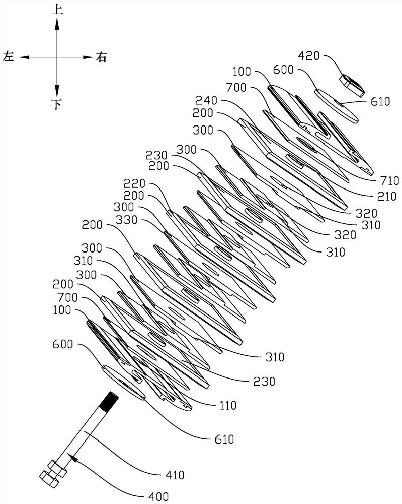
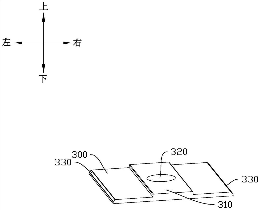
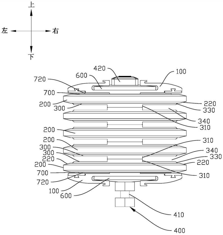
The invention relates to the technical field of electric power, and discloses a bus-intensive connector. The bus-intensive connector comprises connecting plates which are arranged in parallel relatively and are provided with first through holes, an insulating plate provided with second through holes, an aluminum connecting sheet of which the surface is plated with copper and tin, and an insulating bolt; the insulating plate is stacked between the two layers of connecting plates; every two layers of aluminum connecting sheets are arranged between the two adjacent layers of insulating plates, the aluminum connecting sheets are provided with protruding platforms, the platforms corresponding to the aluminum connecting sheets are provided with third through holes, and the thickness of the two overlapped platforms is the same as the thickness of the corresponding bus bar; and the insulating bolt has a screw and a nut. The overall mechanical strength can be improved, the stress area between the aluminum connecting pieces can be increased, stress balance is kept, the situation that the aluminum connecting pieces are bent and deformed is prevented, meanwhile, the thickness of the two platforms is just the same as the thickness of the bus bar, stress between the aluminum connecting pieces and the bus bar is kept balanced, a gap between the aluminum connecting sheet and the bus bar is prevented, and the phenomenon of burnout caused by heating is avoided.

Description

technical field [0001] The invention relates to the technical field of electric power, in particular to a bus bar intensive connector. Background technique [0002] The bus duct is used for the main line of power transmission, and the connector of the bus duct is the connection between the bus duct body unit and the unit, called the connector. Most of the original bus duct connectors have copper conductor connectors or aluminum conductor connectors. Copper connectors can only be used for copper conductor bus ducts, and aluminum conductor connectors can only be used for aluminum conductor bus ducts. Copper conductor busway is expensive, copper resources are scarce, and aluminum conductor busway is low in cost, but aluminum conductor busway is unstable, and it is easy to heat up and burn out at the connector. There are two reasons for this: [0003] 1. Aluminum materials are easily oxidized when exposed to the air, and the surface will be covered with an insulating layer of a...

Claims


Application Information

Patent Timeline
Patent Type & Authority Applications(China)
IPC IPC(8): H02G5/00H01R4/62
CPCH02G5/007H01R4/62
Inventor 郑光乐周作球
Owner 珠海光乐电力母线槽有限公司
Learn More