
Machining method for machining rod head assembly for telescopic oil cylinder based on double vertical clamping

The technology of a telescopic oil cylinder and a processing method, which is applied to the fluid pressure actuating device and other directions, can solve the problems of difficult processing, complex structure, and high rejection rate, and achieve the effect of reducing the problem of processing accuracy and avoiding the difference of reference planes.

Inactive Publication Date: 2022-01-14
CHANGDE JIAHONG MACHINERY
View PDF0 Cites 0 Cited by
  • Summary
  • Abstract
  • Description
  • Claims
  • Application Information

AI Technical Summary

Problems solved by technology

[0002] The rod head assembly is one of the core components of the telescopic hydraulic cylinder of construction machinery. It is mainly used on cranes to provide power for the telescopic boom of the crane through oil pressure; the rod head assembly is a high-precision part with a complex structure. It directly affects whether the oil pressure of the telescopic cylinder of the crane is stable and whether the oil circuit is smooth. If the accuracy does not meet the requirements, it will lead to serious consequences such as oil leakage, balance valve failure, and arm bending.
[0003] In the prior art, the rod head assembly is processed by multiple clamping and positioning, the processing process is long, the processing accuracy is low, and the rejection rate is high. Among them, the rod head assembly is a complex and irregular high-precision part that involves milling, turning , Drilling, welding, grinding and other processes, the process route is long and the processing is difficult, and the processing difficulties are mainly: there are many processing surfaces. In the prior art, only one surface can be processed each time the route is clamped. Repeated clamping and original clamping methods The accuracy of the distance between each hole position relative to the valve core hole cannot be achieved; the size of the valve core hole is the most important quality index of the rod head assembly. In the prior art, the fine boring and chamfering of the valve core hole are clamped with flat pliers, and the flat pliers lock each time after clamping. There will be angular deviation in the position of the workpiece after death, and the maximum deviation of 1mm will be caused during fine boring and chamfering, which will easily cause the deviation of the valve core hole and chamfering position, resulting in the problem of assembly and cutting seals, and the product quality in mass production cannot be guaranteed.
[0004] Moreover, the rocker drill in the prior art uses the auxiliary tooling hole template to fix on the surface of the workpiece, and then visually aligns with the center point of the hole before drilling. The control factors lead to the out-of-tolerance hole size; according to statistics, the hole center size deviation can reach up to 0.58mm
There is a risk of substandard quality
In addition, the radial arm drill of the original rod head assembly process needs to be processed on all 6 surfaces, with many times of clamping and long processing time, requiring 4 sets of equipment for processing

Method used


Image

  • Machining method for machining rod head assembly for telescopic oil cylinder based on double vertical clamping
  • Machining method for machining rod head assembly for telescopic oil cylinder based on double vertical clamping
  • Machining method for machining rod head assembly for telescopic oil cylinder based on double vertical clamping

Examples


Embodiment 1

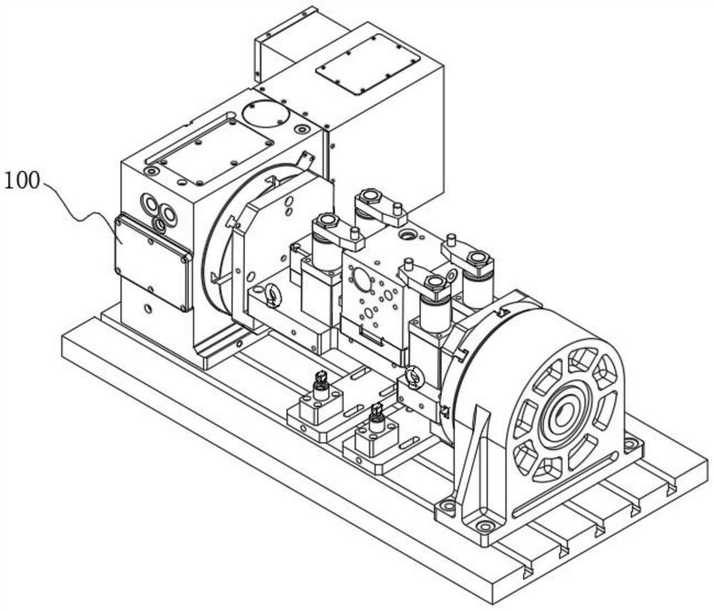
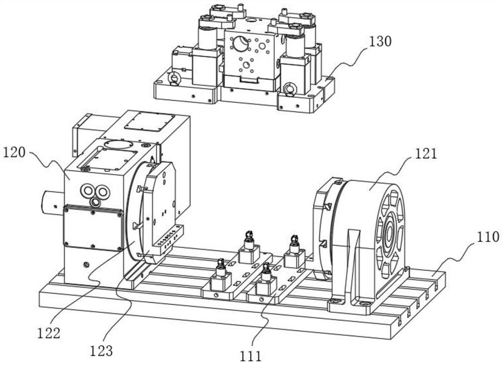
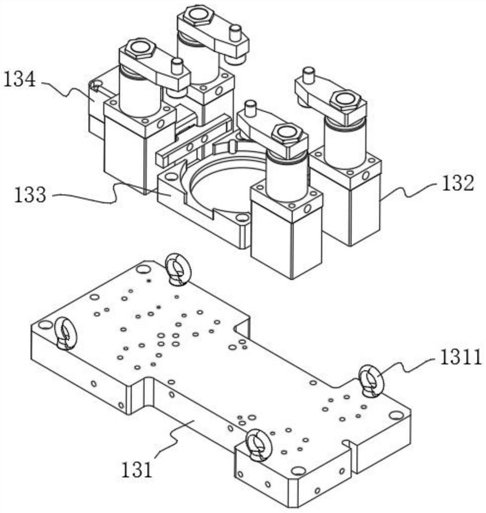
[0075] Considering that the numerical control car takes the milling end face as the benchmark, which leads to the influence of machining accuracy and the high quality risk, this embodiment discloses the multi-face vertical clamping device 100 in S5, please refer to figure 1 with figure 2 As shown, the multi-sided vertical clamping device 100 includes a workbench 110 and a positioning assembly 130 installed on the top of the workbench 110. The two sides of the positioning assembly 130 are respectively provided with a turntable 120 and a tail base 121. The turntable 120 and the tail base 121 are connected to the working The table 110 is fixedly connected, and a turntable 122 is provided on the opposite side of the turntable 120 and the tail base 121. Its main purpose is to drive the positioning assembly 130 to rotate by the drive of the turntable 120. The turntable 120 is specifically driven by four axes to realize the processing of multiple surfaces. , see image 3 As shown, ...

Embodiment 2

[0085] Since the position of the rod head workpiece cannot be guaranteed to be the optimal position after being placed, it needs to be corrected, but considering that it is not only laborious to adjust by hand, but also may cause damage to the workpiece, for this reason, this embodiment discloses a correction part 134 , see image 3 As shown, a correction piece 134 is set between two positioning pieces 132 on one side, please refer to Image 6 As shown, the correction piece 134 includes a correction cylinder 1341 and a correction plate 1343, the correction plate 1343 is fixedly connected to the telescopic end of the correction cylinder 1341, that is, the piston rod of the correction cylinder 1341, and the outside of the correction plate 1343 is slidingly connected with a guide seat 1342, which The main purpose is to support and guide the correction plate 1343, so that the position of the rod head workpiece can be corrected by using the correction plate 1343, so that the correc...

Embodiment 3

[0088] Considering that the external components of the rod head workpiece need to be welded, and the welding must be completed after drilling, but the high temperature during the welding process will cause slight deformation of the material, resulting in the inability to guarantee the processing accuracy of the valve core hole, so the multi-faceted vertical clamping equipment 100 clamping can only carry out rough boring and hook grooves on the valve core hole, and it needs to be clamped again to carry out fine boring on the valve core hole. Therefore, this embodiment discloses the single-sided vertical clamping device 200 in S10. Please refer to Figure 8 As shown, the single-sided vertical clamping device 200 includes a base 210. The base 210 is an "L"-shaped structure, thereby forming two vertical and horizontal support surfaces. The vertical support surface of the base 210 is symmetrically provided with two A stopper 220, a single-sided positioning plate 230 is arranged betw...


PUM


Abstract

The invention relates to the technical field of rod head machining, in particular to a machining method for machining a rod head assembly for a telescopic oil cylinder based on double vertical clamping. The method comprises the following steps: blanking: cutting a long steel square rod into square rod workpieces required by processing; milling: milling five surfaces of the square rod workpiece to obtain a rod head workpiece; multi-surface vertical clamping: clamping the rod head workpiece by using multi-surface vertical clamping equipment by taking the center of the rod head workpiece as a reference; and single-side vertical clamping: clamping the rod head workpiece by using single-side vertical clamping equipment by taking the center of the rod head workpiece as a reference. The single-side vertical clamping equipment and the multi-surface vertical clamping equipment both take the circle center of a boss or a concave table of a workpiece as a datum point, so that the influence of the milling face dimensional tolerance on the machining precision is avoided; a single-side positioning plate and a multi-surface positioning plate are matched, so that machining is conducted through the same datum plane, and the problem of machining precision caused by different reference surfaces and repeated clamping is solved.

Description

technical field [0001] The invention relates to the technical field of rod head processing, in particular to a processing method for processing a rod head assembly for a telescopic oil cylinder based on a double vertical mounting clamp. Background technique [0002] The rod head assembly is one of the core components of the telescopic hydraulic cylinder of construction machinery. It is mainly used on cranes to provide power for the telescopic boom of the crane through oil pressure; the rod head assembly is a high-precision part with a complex structure. It directly affects whether the oil pressure of the telescopic cylinder of the crane is stable and whether the oil circuit is smooth. If the accuracy does not meet the requirements, it will lead to serious consequences such as oil leakage, balance valve failure, and arm bending. [0003] In the prior art, the rod head assembly is processed by multiple clamping and positioning, the processing process is long, the processing ac...

Claims


Application Information

Patent Timeline
Patent Type & Authority Applications(China)
IPC IPC(8): B23P15/00
CPCB23P15/00F15B15/1457
Inventor 谭宇岐铁钟刘勇
Owner CHANGDE JIAHONG MACHINERY
Learn More