Method for preparing direct reduced iron by feeding hydrogen into reduction shaft furnace

A technology for reducing iron and shaft furnaces, applied in shaft furnaces, furnaces, furnace types, etc., can solve the problems of lower furnace charge temperature and lower production efficiency, and achieve the effects of increased productivity and stable temperature

Active Publication Date: 2022-01-14
NORTHEASTERN UNIV
View PDF8 Cites 1 Cited by
  • Summary
  • Abstract
  • Description
  • Claims
  • Application Information

AI Technical Summary

Problems solved by technology

[0009] In order to solve the above-mentioned problems in the prior art, the present invention provides a method for preparing direct reduced iron by entering hydrogen into the reduction shaft furnace, which solves the problem that the hydrogen reduction heat absorption in the high-purity hydrogen shaft furnace direct reduction process causes the temperature of the charge to drop rapidly, resulting in a decrease in production efficiency The problem

Method used


Image

  • Method for preparing direct reduced iron by feeding hydrogen into reduction shaft furnace
  • Method for preparing direct reduced iron by feeding hydrogen into reduction shaft furnace
  • Method for preparing direct reduced iron by feeding hydrogen into reduction shaft furnace

Examples


Embodiment 1

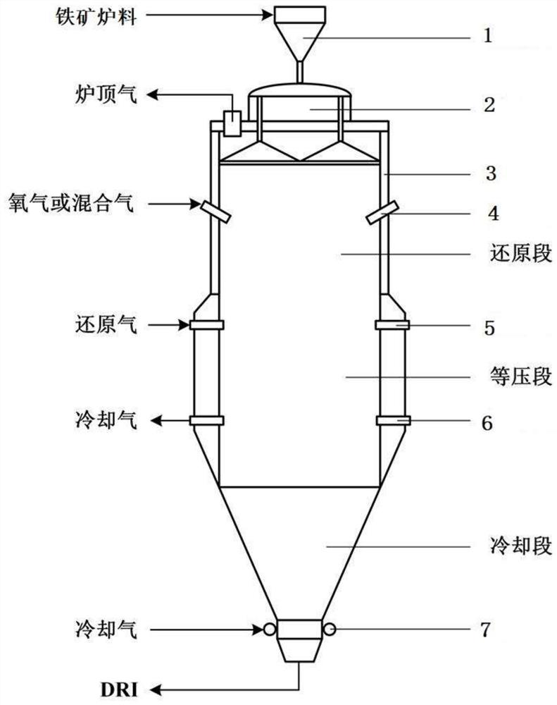
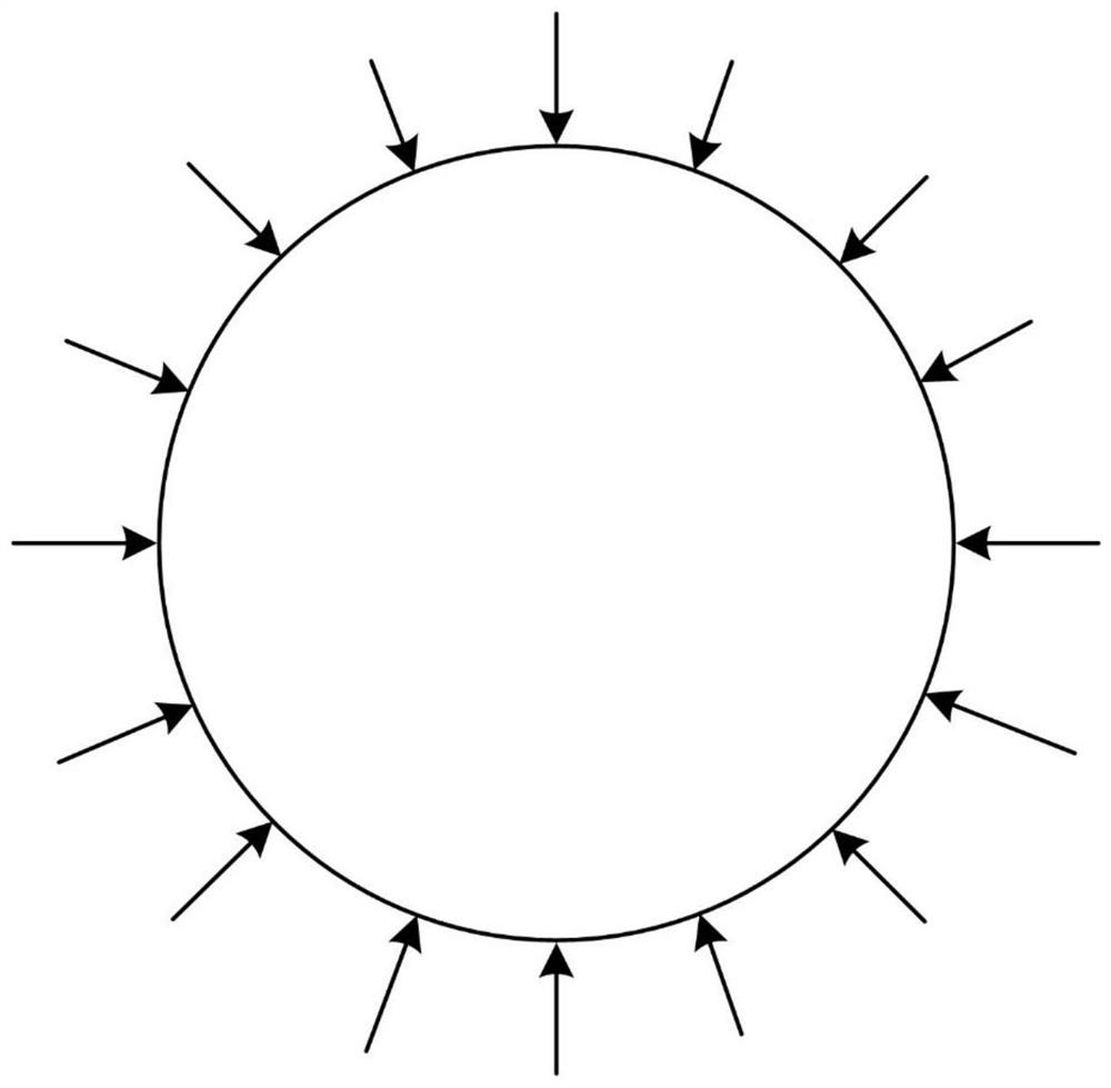
[0065] In the method in which hydrogen gas enters the reduction shaft furnace to prepare direct reduced iron provided in this embodiment, combustion injection devices 4 are uniformly arranged on the upper part of the furnace body surrounding the reduction section of the shaft furnace, and the distance between adjacent combustion injection devices 4 is 0.8 meters, such as image 3 As shown, the direction of the jet of oxygen injected by the combustion injection device 4 is downward and the included angle with the shaft furnace body is 45°. Make the heat disperse and distribute, and prevent local overheating from causing iron-containing minerals to bond.

[0066] The method that the hydrogen gas enters the reduction shaft furnace provided in this example to prepare direct reduced iron uses iron-containing ore powder with a total iron grade of 68% and iron-containing concentrate lump ore with a total iron grade of 66% as raw materials, wherein the iron-containing ore The proporti...

Embodiment 2

[0074] In the method in which hydrogen gas enters the reduction shaft furnace to prepare direct reduced iron provided in this embodiment, combustion injection devices 4 are evenly arranged on the upper part of the furnace body surrounding the reduction section of the shaft furnace, and the distance between adjacent combustion injection devices 4 is 0.6 meters. The jet flow direction of the oxygen injection device 4 is downward and the included angle with the shaft furnace body is 30°. Make the heat disperse and distribute, and prevent local overheating from causing iron-containing minerals to bond.

[0075] The method that the hydrogen gas enters the reduction shaft furnace provided in this example to prepare direct reduced iron uses iron-containing ore powder with a total iron grade of 69.1% and iron-containing concentrate ore with a total iron grade of 65.7% as raw materials, wherein the iron-containing ore The proportion of particles below 200 mesh in the powder is 86%, inc...


PUM

PropertyMeasurementUnit
strengthaaaaaaaaaa
strengthaaaaaaaaaa
particle sizeaaaaaaaaaa

Abstract

The invention provides a method for preparing direct reduced iron by feeding hydrogen into a reduction shaft furnace. Combustion injection blowing devices are uniformly arranged around a furnace body of a reduction section of the shaft furnace. The method comprises the following steps that S1, a furnace charge containing iron is fed into the shaft furnace, and meanwhile, hot reducing gas is continuously fed into the reduction section of the shaft furnace to reduce the furnace charge containing iron, wherein hydrogen in the hot reducing gas accounts for 80% or above of the reducing gas; and S2, in the reduction process of the furnace charge containing iron, according to the temperature of the furnace charge containing iron in the reduction section of the shaft furnace, the combustion injection blowing devices inject oxygen into the reduction section of the shaft furnace. The problem that in a high-purity hydrogen shaft furnace direct reduction technology, due to the fact that the furnace charge temperature can be rapidly reduced through hydrogen reduction heat absorption, the production efficiency is reduced is solved.

Description

technical field [0001] The invention belongs to the technical field of metallurgy and chemical industry, and in particular relates to a method for preparing direct reduced iron by entering hydrogen gas into a reduction shaft furnace. Background technique [0002] With the rapid development of the global steel industry, low-carbon production has become the new competitiveness of the steel industry. Hydrogen metallurgy is the use of hydrogen instead of carbon as a reducing agent, and the reduction product is clean water. It is a new technology to reduce carbon dioxide emissions. The use of hydrogen energy can beneficially promote the green and sustainable development of the steel industry. Hydrogen is the most active reducing agent among the reducing agents. When the reduction temperature is higher than 810°C, the ability of hydrogen to reduce iron ore is greater than that of CO. Therefore, vigorously developing hydrogen metallurgy will change the use of carbon as a reducing a...

Claims


Application Information

Patent Timeline
Patent Type & Authority Applications(China)
IPC IPC(8): C21B13/02
CPCC21B13/02C21B13/0073Y02P10/143
Inventor 吕炜储满生唐珏柳政根周渝生王国栋
Owner NORTHEASTERN UNIV
Why Eureka
Try Eureka