
Chip electronic component tin plating solution and tin electroplating method

A technology of electronic components and tin plating solution, applied in the direction of electrolytic components, electrolytic process, cells, etc., can solve the problems of poor solderability and solder resistance, rough crystallization of tin layer, weak oxidation resistance of tin layer, etc., to achieve Good solderability and solder resistance, smooth tin layer appearance, and smooth microscopic appearance

Pending Publication Date: 2022-01-14
广东羚光新材料股份有限公司
View PDF11 Cites 1 Cited by
  • Summary
  • Abstract
  • Description
  • Claims
  • Application Information

AI Technical Summary

Problems solved by technology

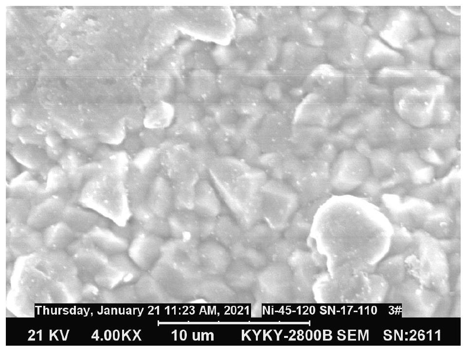
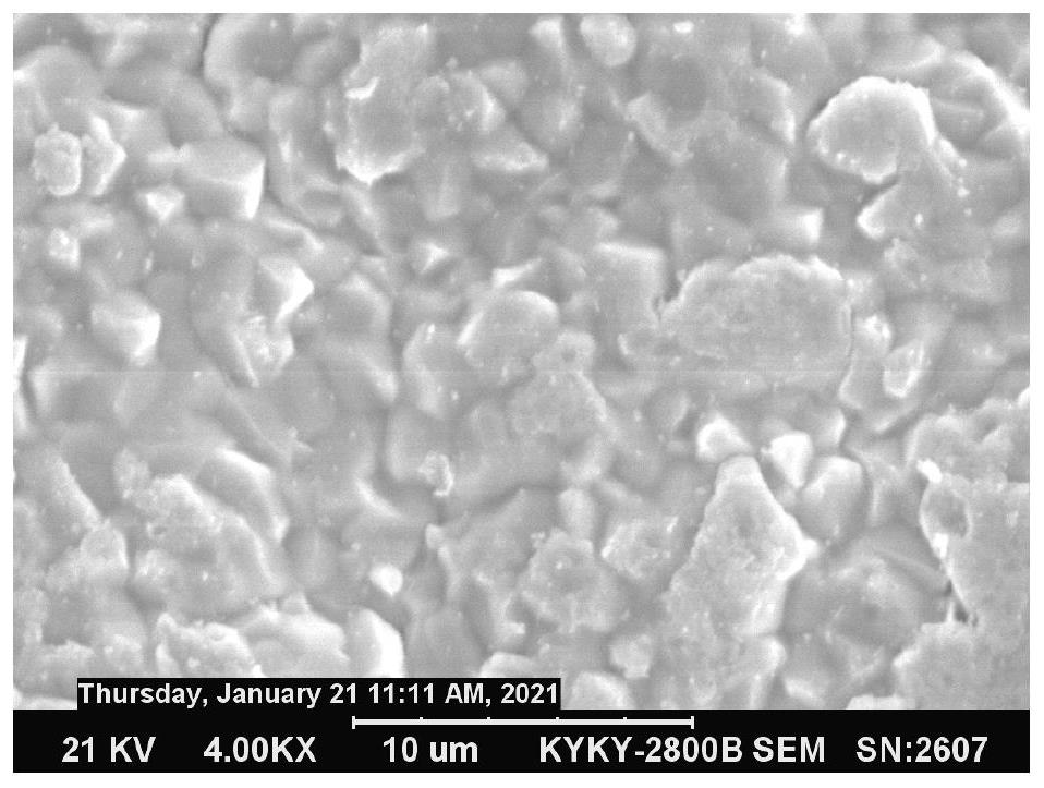
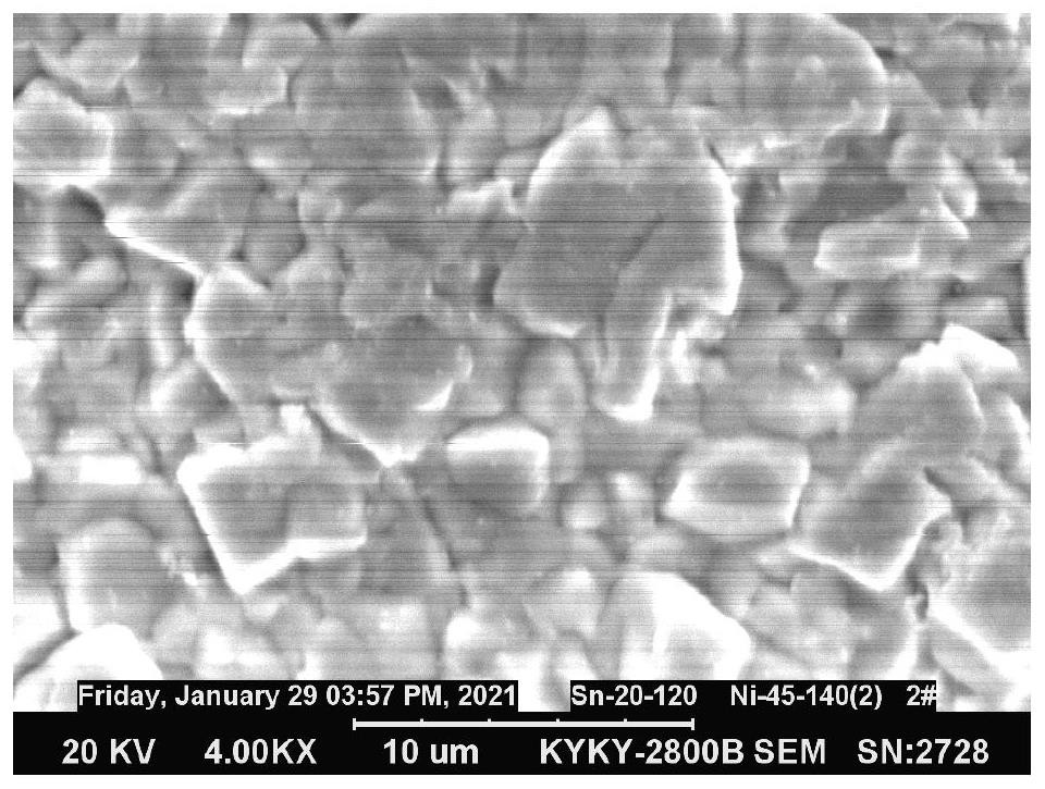
0201, 01005 and other types of chip components, due to the small size, the terminal electrode part for the lead wire is also very small, resulting in the following problems when using conventional tin electroplating technology: long time for electroplating, large energy loss; low current efficiency , hydrogen evolution is serious during the electroplating process, and it is easy to leave pores in the tin layer, which directly affects the welding performance of the product; the tin layer of the product obtained by electroplating has rough crystallization, uneven grains, poor flatness, and many pores, resulting in a high void rate during product welding , poor solderability and solder resistance; the tin layer formed by traditional electroplating tin bath and electroplating technology has weak oxidation resistance, and is prone to oxidation and discoloration of the tin layer, shortening the service life and storage period of electronic components

Method used


Image

  • Chip electronic component tin plating solution and tin electroplating method
  • Chip electronic component tin plating solution and tin electroplating method
  • Chip electronic component tin plating solution and tin electroplating method

Examples


Embodiment 1

[0040] A tin-plating solution for chip electronic components uses water as a solvent, and its components and concentrations are shown in Table 1. Use this tin plating solution to perform tin electroplating on 0201 chip resistors: at a temperature of 25°C, adjust the pH value of the plating solution to 4.2, and the current density to 0.4A / dm 2 , electroplating for 100 min, to obtain an electroplated product.

Embodiment 2

[0042] A tin-plating solution for chip electronic components uses water as a solvent, and its components and concentrations are shown in Table 1. Use this tin plating solution to perform tin electroplating on 0201 chip resistors: at a temperature of 25°C, adjust the pH value of the plating solution to 4.2, and the current density to 0.4A / dm2 , electroplating for 100 min, to obtain an electroplated product.

Embodiment 3

[0044] A tin-plating solution for chip electronic components uses water as a solvent, and its components and concentrations are shown in Table 1. Use this tin plating solution to perform tin electroplating on 0201 chip resistors: at a temperature of 25°C, adjust the pH value of the plating solution to 4.2, and the current density to 0.4A / dm 2 , electroplating for 100 min, to obtain an electroplated product.


PUM

PropertyMeasurementUnit
concentrationaaaaaaaaaa

Abstract

The invention provides a chip electronic component tin plating solution and a tin electroplating method, and relates to the technical field of chip electronic components. The tin plating solution comprises the following components with the working concentration: 5-20 g / L of main salt, 50-250 g / L of conducting salt, 20-150 g / L of a complexing agent and 1-20 g / L of an additive. According to the tin electroplating method, the tin plating solution is adopted for plating tin on a chip component. According to the tin plating solution, the overall conductivity of the electroplating solution can be improved, the current efficiency is improved, an obtained tin layer is fine in crystallization, uniform in thickness and flat and smooth in appearance, and excellent weldability and welding resistance are achieved.

Description

technical field [0001] The invention relates to the technical field of chip electronic components, in particular to a tin plating solution and a tin electroplating method for chip electronic components. Background technique [0002] Tin is a silver-white metal with the advantages of low melting point, easy welding, non-toxicity, strong stability, anti-tarnish, softness and good ductility, etc. It has a wide range of uses. In the field of electronic components, tin is one of the important materials for surface treatment materials of solderable terminal electrodes of electronic components. The main application method of tin is electroplating to form a film, that is, in the electroplating solution, through the action of current, the pure tin anode undergoes a hydrolysis reaction, and the surface of the terminal electrode undergoes a Faraday reaction and deposits to form a pure tin film. [0003] In recent years, with the rapid development of science and technology, electronic ...

Claims


Application Information

Patent Timeline
Patent Type & Authority Applications(China)
IPC IPC(8): C25D3/32C25D21/12
CPCC25D3/32C25D21/12
Inventor 梁太平娄红涛玉海斌丁美蓉万广宇刘名惠罗家段
Owner 广东羚光新材料股份有限公司
Learn More