
Airplane skin part detection method and device

A technology of aircraft skinning and detection methods, applied in computer parts, image data processing, instruments, etc., can solve problems such as fatigue, delamination, damage, etc.

Pending Publication Date: 2022-01-14
NANJING UNIV OF AERONAUTICS & ASTRONAUTICS +1
View PDF0 Cites 0 Cited by
  • Summary
  • Abstract
  • Description
  • Claims
  • Application Information

AI Technical Summary

Problems solved by technology

(1) Defects generated during the molding process: In the manufacturing process of the composite material structure, under certain process conditions, the matrix resin and the reinforced fabric fibers are evenly mixed and combined well, and the fibers and resins, and the lay-up and lay-up directly reach the expected Interfacial bonding strength
Under the given process conditions such as temperature and pressure, the viscosity of the matrix resin will change significantly with the change of curing temperature. When the curing parameters are unreasonably optimized or fluctuate or deviate, the resin fluidity and penetration may be affected. properties and the bonding interface quality between fiber and resin, ply and ply, in severe cases, defects such as delamination and pores will occur
(2) Defects generated during the assembly process: the assembly process refers to the connection between the rib and the skin, or the connection between the rib and the skin, usually by drilling and riveting.
However, this method will cause damage, and the damage mechanism is different. Drilling or scribing dimples will cause thermal fatigue and stress fatigue in the contact between the skin and the drill bit.

Method used


Image

  • Airplane skin part detection method and device
  • Airplane skin part detection method and device
  • Airplane skin part detection method and device

Examples


Embodiment Construction

[0037] The following will clearly and completely describe the technical solutions in the embodiments of the present invention with reference to the accompanying drawings in the embodiments of the present invention. Obviously, the described embodiments are only some, not all, embodiments of the present invention. Based on the embodiments of the present invention, all other embodiments obtained by persons of ordinary skill in the art without making creative efforts belong to the protection scope of the present invention.

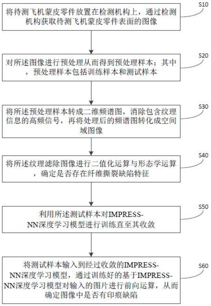
[0038] refer to figure 1 , the present embodiment provides a method for detecting aircraft skin parts, comprising the following steps:

[0039] S10: placing the aircraft skin part to be tested on the detection mechanism, and obtaining an image of the surface of the aircraft skin part to be tested through the detection mechanism;

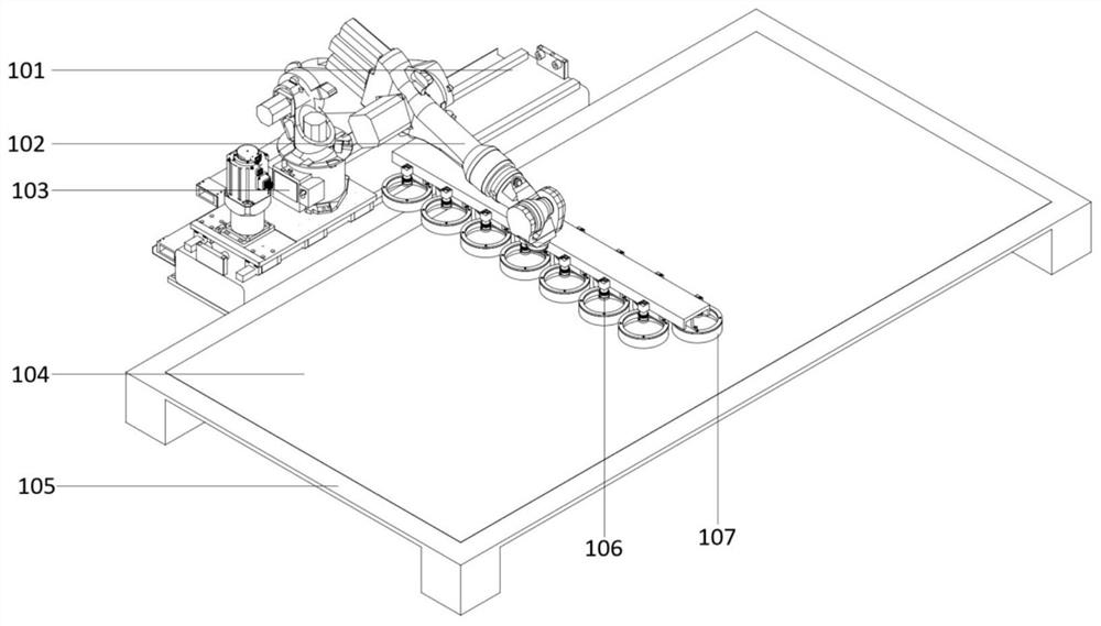
[0040] Specifically, such as figure 2 As shown, the detection mechanism includes the robot ground rail 101, which is connected w...


PUM


Abstract

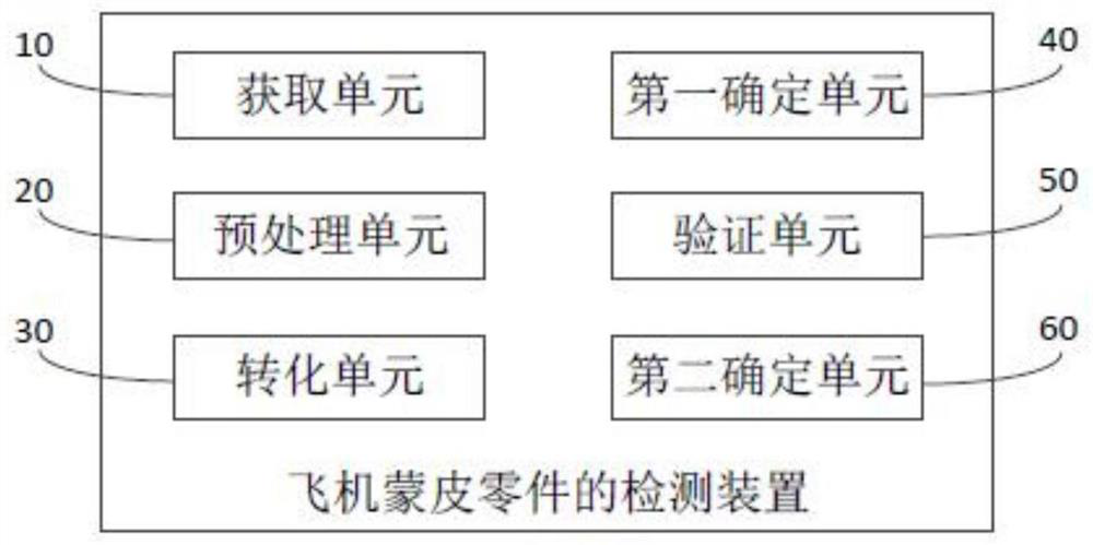
The invention discloses an aircraft skin part detection method and device, and the method comprises the steps of obtaining an image of the surface of a to-be-detected aircraft skin part through a detection mechanism; preprocessing the image to obtain a preprocessed sample; converting the preprocessed sample into a two-dimensional spectrogram, eliminating a high-frequency signal containing texture information, and converting the processed spectrogram into a spatial domain image; carrying out binarization operation and morphological operation on the texture filtered image to determine whether a fiber tearing defect feature exists or not; training an IMPRESS-NN deep learning model by using the test sample until the IMPRESS-NN deep learning model is converged; and inputting a test sample into the converged IMPRESS-NN deep learning model so as to determine whether the image has an impression defect or not. According to the method, the imprint defects on the aircraft skin part are marked through the IMPRESS-NN, and automatic online detection of the surface defects is achieved; the preprocessed image is converted into a two-dimensional spectrogram, so that whether tearing exists or not is detected.

Description

technical field [0001] The invention relates to the field of detection of aircraft skin parts, in particular to a detection method and device for aircraft skin parts. Background technique [0002] In recent years, with the energy saving and weight reduction of aviation materials, high-performance composite materials have been widely used in aircraft skins, such as radome, radio radome, aileron, part of the wing, horizontal tail and vertical tail, and part of the fuselage Skins are mostly made of composite materials. Most of the composite materials used in aircraft skins are epoxy carbon fiber composite materials, which can withstand high temperature, friction, electrical conduction, heat conduction and corrosion resistance, and exhibit high strength along the fiber axis. Composite materials made of carbon fiber and epoxy resin have low relative density, good rigidity and high strength, and have been widely used in aircraft structural materials. [0003] In the manufacturin...

Claims


Application Information

Patent Timeline
Patent Type & Authority Applications(China)
IPC IPC(8): G06T7/00G06V10/774G06K9/62G06N3/04
CPCG06T7/0002G06N3/045G06F18/214
Inventor 陆永华朱华煜徐嘉骏卢正威刘昕昱高铖
Owner NANJING UNIV OF AERONAUTICS & ASTRONAUTICS
Learn More