
Multi-beam Luneberg lens antenna based on double-layer artificial medium, control method and application

A Luneberg lens antenna and artificial medium technology, applied in antennas, electrical components, etc., can solve the problems of sharp drop in beam gain, difficulty in ensuring the feed source, and affecting the edge strength of the cylindrical Luneberg lens, and achieve simple processing and accurate focusing and the effect of antenna performance improvement

Pending Publication Date: 2022-01-14
中国电波传播研究所 +1
View PDF0 Cites 1 Cited by
  • Summary
  • Abstract
  • Description
  • Claims
  • Application Information

AI Technical Summary

Problems solved by technology

[0005] The difficulty in solving the above problems and defects is: In terms of wide beam formation, if the feed beam is changed by changing the shape of the feed horn, and then the beam width of the azimuth plane of the Lunberg lens antenna is widened, it is difficult to ensure that the feed is relatively wide. An approximate point source, in a divergent state, it is difficult to guarantee the gain, and the beam gain still shows a large steep drop as it leaves the axis
In terms of actual processing, the conventional method of drilling holes on a single high-dielectric constant medium, at the edge, due to the large difference between the dielectric constant of the substrate and the theoretically required dielectric constant, the corresponding distribution of holes is denser. , greatly affects the strength of the edge of the cylindrical Lunberg lens
In addition, the phase center of the feed horn is often embedded inside the horn, and there is a conflict between the physical lens and the horn, so that the phase center of the horn cannot be located on the focal line of the lens

Method used


Image

  • Multi-beam Luneberg lens antenna based on double-layer artificial medium, control method and application
  • Multi-beam Luneberg lens antenna based on double-layer artificial medium, control method and application
  • Multi-beam Luneberg lens antenna based on double-layer artificial medium, control method and application

Examples


Embodiment Construction

[0038] In order to make the object, technical solution and advantages of the present invention more clear, the present invention will be further described in detail below in conjunction with the examples. It should be understood that the specific embodiments described here are only used to explain the present invention, not to limit the present invention.

[0039] Aiming at the problems existing in the prior art, the present invention provides a multi-beam Lunberg lens antenna based on a double-layer artificial medium, a control method and its application. The present invention will be described in detail below in conjunction with the accompanying drawings.

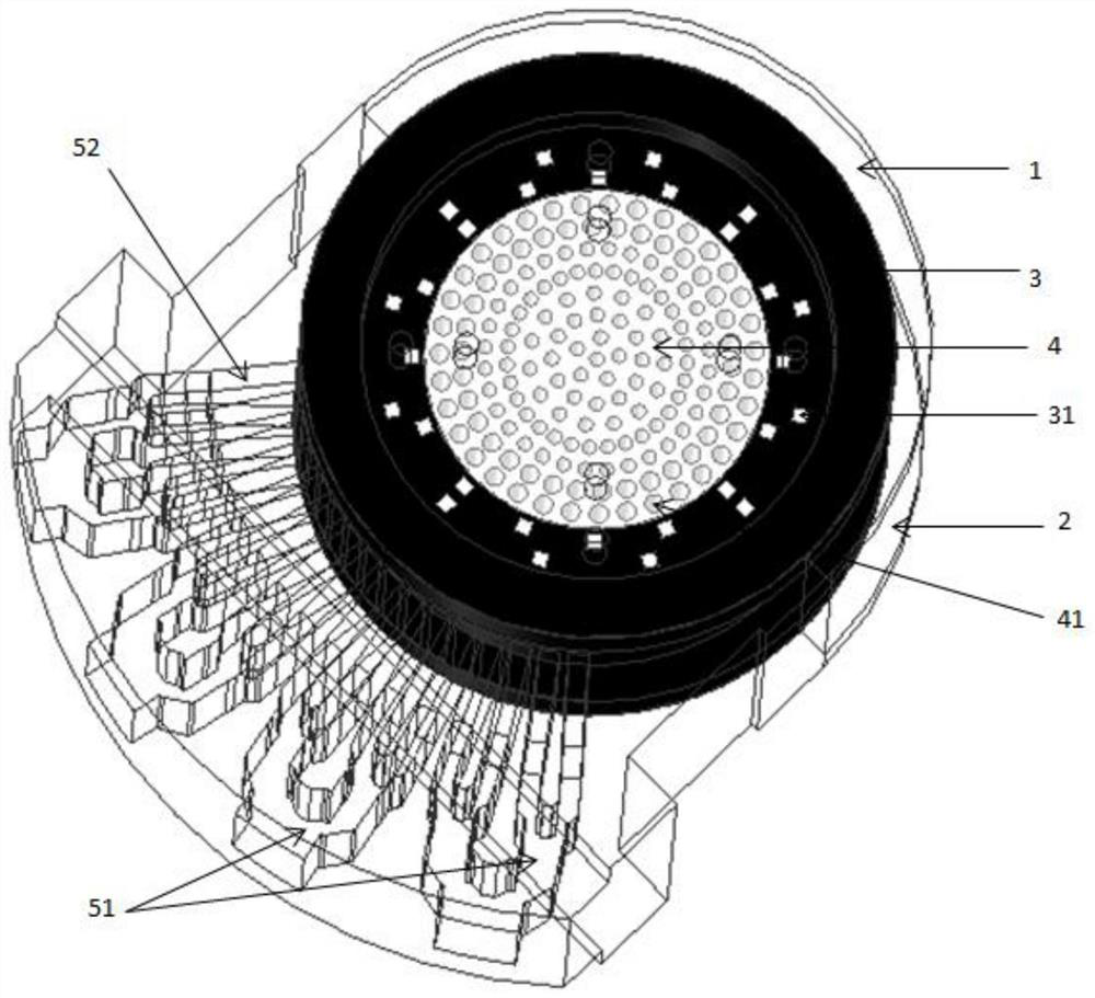
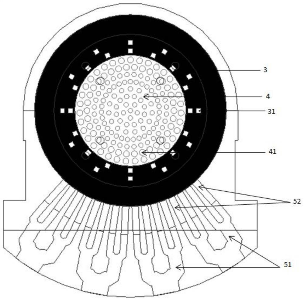
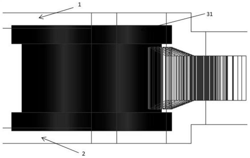
[0040] Such as figure 1 , figure 2 with image 3 As shown, the double-layer artificial medium multi-beam Lunberian lens antenna provided by the present invention includes an upper cover 1 , a lower cover 2 , and a Lunberian lens and a feeding system between the upper and lower covers. The Lunberg lens is divided into ...


PUM


Abstract

The invention belongs to the technical field of antennas, and discloses a multi-beam Luneberg lens antenna based on a double-layer artificial medium, a control method and an application. The antenna comprises an upper cover plate, a lower cover plate, a cylindrical Luneberg lens and a feed system. The cylindrical luneberg lens is divided into an inner layer and an outer layer, and the overall gradual change dielectric constant effect is achieved in the mode that holes are punched in the inner layer high dielectric constant medium and the outer layer low dielectric constant medium is filled. The feed system comprises a waveguide power divider and a feed horn. And by utilizing the design that the periphery of the lens is air, the tail end of the horn is embedded into the lens to ensure that the phase center coincides with the focal line of the lens. The feed system and the two cover plates jointly play a role in fixing and feeding. According to the invention, lens processing is more concise and focusing is more accurate, and a feed mode of combining a power divider with a plurality of small-size horns is further utilized so that azimuth plane beam width which is wider than that of single horn feed is realized; and rapid scanning coverage in a wide angular domain can be realized by using fewer feed ports and switching of switches.

Description

technical field [0001] The invention belongs to the technical field of antennas, and in particular relates to a multi-beam Lunberg lens antenna based on a double-layer artificial medium, a control method and an application. Background technique [0002] At present, radio systems represented by satellite communications, radar detection, and electronic countermeasures have more and more demands for multi-beam antennas. Specifically, in these applications, the antenna system needs to form multiple beams at the same time or time-sharing to cover a certain area in space to meet the communication, detection, navigation, and interference requirements of the system in a large space area. In order to ensure signal transmission quality and transmission rate, synchronization often requires the antenna to have a wide beam width and a wide frequency band. The beam scanning system based on the phased array has a strong advantage in beam control, but the phased array system is expensive o...

Claims


Application Information

Patent Timeline
Patent Type & Authority Applications(China)
IPC IPC(8): H01Q15/08H01Q19/06
CPCH01Q15/08H01Q19/06
Inventor 张照许鑫葛薇吴燕民张鹏飞
Owner 中国电波传播研究所
Learn More