Antenna interconnection structure with good grounding

A technology with good grounding and interconnection structure, applied in antennas, antenna arrays, antenna components and other directions, can solve problems such as poor transmission stability, large signal energy loss, poor maintainability, etc. The effect of reducing signal energy loss

Active Publication Date: 2022-01-18
CHENGDU RDW TECH CO LTD
View PDF13 Cites 1 Cited by
  • Summary
  • Abstract
  • Description
  • Claims
  • Application Information

AI Technical Summary

Problems solved by technology

[0003] 1. Poor maintainability
The traditional multilayer microwave board and the antenna array are interconnected by welding. Both ends of the insulator are connected by welding. In the later maintenance of the array, the multilayer microwave board is inconvenient to disassemble. Easy to damage after disassembly and repair, not conducive to maintenance and testing
[0004] 2. In the traditional radar or communication antenna system, the RF chip is bonded to the cavity, and there is a ground discontinuity problem at the connection between the RF chip and the multi-layer microwave board, resulting in unsatisfactory matching at the transition, poor grounding effect, and signal energy loss Big
However, there are still problems of large signal energy loss and poor transmission stability

Method used


Image

  • Antenna interconnection structure with good grounding
  • Antenna interconnection structure with good grounding

Examples


Embodiment 1

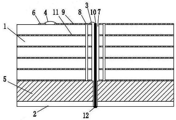
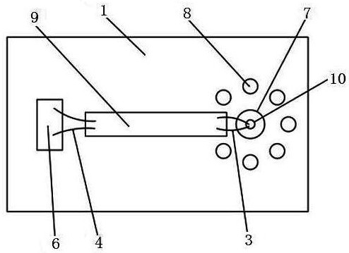
[0033] see figure 1 with figure 2 , a well-grounded antenna interconnection structure, including a multilayer microwave board 1 and an antenna array 2, and also includes a first bonding gold wire 3, a second bonding gold wire 4 and a heat dissipation cavity 5, the multilayer microwave board 1 is A radio frequency circuit board with at least two conductive layers stacked, the multilayer microwave board 1 is fixed on the top of the heat dissipation cavity 5, the antenna array 2 is fixed on the bottom of the heat dissipation cavity 5, and the multilayer microwave board 1 is bonded with The chip 6 is provided with a conduction hole 7 and a coaxial ground hole 8 on the multilayer microwave board 1, and the conduction hole 7 and the coaxial ground hole 8 communicate with the heat dissipation cavity 5 respectively. The microstrip line 9 and the insulator 10, the coaxial ground hole 8 is respectively connected to the microstrip line 9 and the ground 11 of the microstrip line, and on...

Embodiment 2

[0036] see figure 1 with figure 2 , a well-grounded antenna interconnection structure, including a multilayer microwave board 1 and an antenna array 2, and also includes a first bonding gold wire 3, a second bonding gold wire 4 and a heat dissipation cavity 5, the multilayer microwave board 1 is A radio frequency circuit board with at least two conductive layers stacked, the multilayer microwave board 1 is fixed on the top of the heat dissipation cavity 5, the antenna array 2 is fixed on the bottom of the heat dissipation cavity 5, and the multilayer microwave board 1 is bonded with The chip 6 is provided with a conduction hole 7 and a coaxial ground hole 8 on the multilayer microwave board 1, and the conduction hole 7 and the coaxial ground hole 8 communicate with the heat dissipation cavity 5 respectively. The microstrip line 9 and the insulator 10, the coaxial ground hole 8 is respectively connected to the microstrip line 9 and the ground 11 of the microstrip line, and on...

Embodiment 3

[0040] see figure 1 with figure 2, a well-grounded antenna interconnection structure, including a multilayer microwave board 1 and an antenna array 2, and also includes a first bonding gold wire 3, a second bonding gold wire 4 and a heat dissipation cavity 5, the multilayer microwave board 1 is A radio frequency circuit board with at least two conductive layers stacked, the multilayer microwave board 1 is fixed on the top of the heat dissipation cavity 5, the antenna array 2 is fixed on the bottom of the heat dissipation cavity 5, and the multilayer microwave board 1 is bonded with The chip 6 is provided with a conduction hole 7 and a coaxial ground hole 8 on the multilayer microwave board 1, and the conduction hole 7 and the coaxial ground hole 8 communicate with the heat dissipation cavity 5 respectively. The microstrip line 9 and the insulator 10, the coaxial ground hole 8 is respectively connected to the microstrip line 9 and the ground 11 of the microstrip line, and one...


PUM


Abstract

The invention discloses an antenna interconnection structure with good grounding, and belongs to the field of radar communication. The structure comprises a multi-layer microwave plate and an antenna array, and is characterized in that the structure also comprises a first gold bonding wire, a second gold bonding wire and a heat dissipation cavity; a chip is bonded on the multi-layer microwave plate, the multi-layer microwave plate is provided with a via hole and a coaxial ground hole, the multilayer microwave plate is provided with a microstrip line and an insulator, one end of the insulator passes through a via hole of the multilayer microwave plate and is connected with the microstrip line on the multilayer microwave plate through a first bonding gold wire, the other end of the insulator passes through the heat dissipation cavity and is welded with the antenna array, and the chip is connected with the microstrip line through a second bonding gold wire; the insulator is provided with a welding point, the antenna array is welded on the welding point, and the upper end face of the insulator and the microstrip line are located on the same horizontal plane. According to the invention, signal energy loss can be greatly reduced, and signal transmission stability and use reliability are effectively guaranteed.

Description

technical field [0001] The invention relates to the technical field of radar communication, in particular to an antenna interconnection structure with good grounding. Background technique [0002] The radio frequency microwave signal interconnection structure is applied in the radar or communication antenna system to realize the transmission of microwave radio frequency signals. The traditional multilayer microwave board and the antenna array are directly connected by welding, which has the following defects: [0003] 1. Poor maintainability. The traditional multilayer microwave board and the antenna array are interconnected by welding. Both ends of the insulator are connected by welding. In the later maintenance of the array, the multilayer microwave board is inconvenient to disassemble. It is easily damaged after disassembly and repair, which is not conducive to maintenance and testing. [0004] 2. In the traditional radar or communication antenna system, the RF chip is ...

Claims


Application Information

Patent Timeline
Patent Type & Authority Applications(China)
IPC IPC(8): H01Q1/22H01Q1/48H01Q21/00H01Q1/00H05K7/20
CPCH01Q1/22H01Q1/48H01Q21/00H01Q1/02
Inventor 余正冬赵鹏刘雪颖章圣长赵云唐琳郭宏展
Owner CHENGDU RDW TECH CO LTD
Why Eureka
Try Eureka