Decoupling antenna housing applied to dual-polarized antenna array and antenna device

A technology of dual-polarized antennas and antenna arrays, applied in the directions of antenna arrays, individually powered antenna arrays, antenna coupling, etc., can solve the problems of affecting the radiation characteristics of antenna arrays and the inability to use decoupling methods, and achieve the effect of improving isolation

Pending Publication Date: 2022-01-18
ZTE CORP +1
View PDF1 Cites 0 Cited by
  • Summary
  • Abstract
  • Description
  • Claims
  • Application Information

AI Technical Summary

Problems solved by technology

However, because this technology needs to add an additional decoupling structure between the antenna units, this decoupling method also has certain requirements for the distance between the antenna units, which cannot be smaller than the size of the decoupling metamaterial unit, otherwise it will not be possible to use this decoupling method
[0004] Another example is a new type of decoupling structure applied to the Ka-band disclosed in "Decoupling Structure Design of Ka-band Array Antenna", which is to establish a "d"-shaped coplanar compact electromagnetic bandgap ( UC-EBG) structure achieves the decoupling effect, but this decoupling structure will radiate electromagnetic fields outward after the induced current is generated, which will inevitably affect the original radiation characteristics of the antenna array

Method used


Image

  • Decoupling antenna housing applied to dual-polarized antenna array and antenna device
  • Decoupling antenna housing applied to dual-polarized antenna array and antenna device
  • Decoupling antenna housing applied to dual-polarized antenna array and antenna device

Examples


Embodiment 1

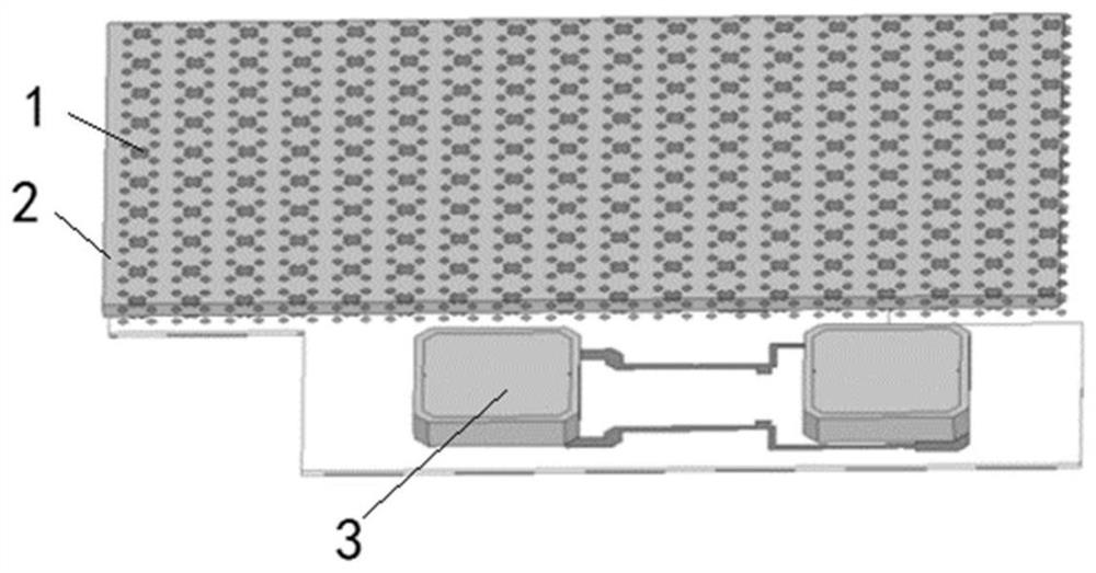
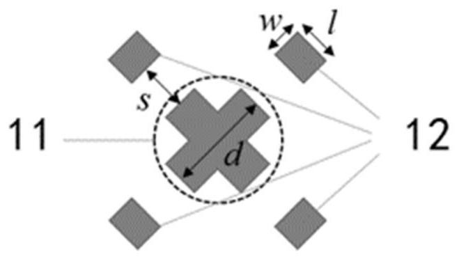
[0040]Decoupling the antenna cover according to the present embodiment is applied to a dual-polarized antenna array comprising: a radome 2; provided on metal patch array antenna cover 2. An array of metallic patches each patch unit 1 uses the metal cross-shaped patch element, comprising: a main reflector sheet 11, a plurality of auxiliary reflection sheet 12, and a plurality of auxiliary reflective sheet 12 disposed at the main reflection sheet 11 and an outer periphery of a uniform distribution at certain intervals.

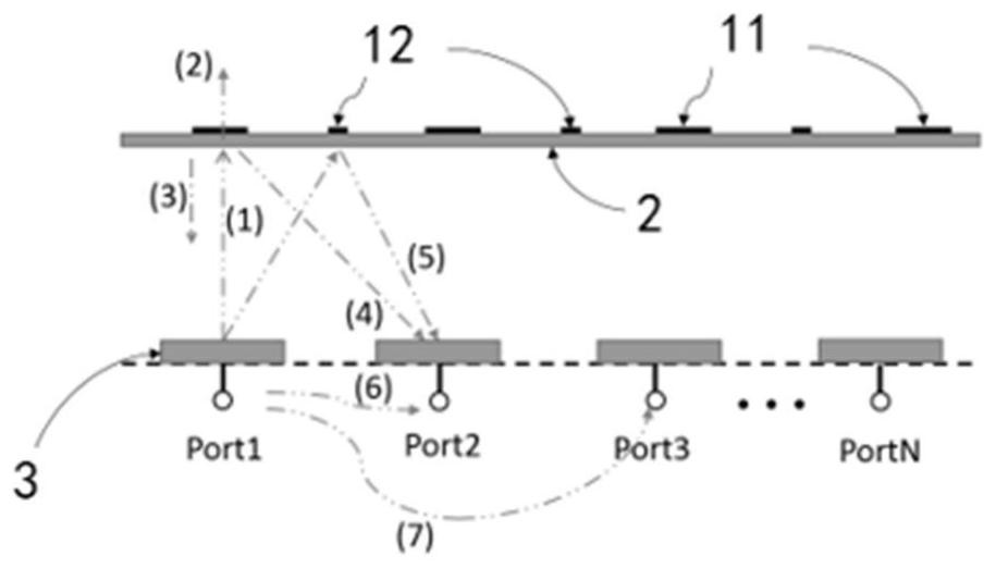
[0041] Specifically, the working principle of decoupling the present embodiment as a schematic view of the radome image 3 , The antenna cover is a layer of low loss, low dielectric constant substrate made (i.e., above the F4B PTFE sheet), the top of the radome (surface remote from the antenna array) printed with a plurality of periodic metal the reflective sheet (i.e., metal patch unit), the metal reflection plate includes a primary reflective sheet 11, a plurality ...

Embodiment 2

[0052] 1 is substantially the same structure as the embodiment of the present embodiment is applied to the radome decoupling of dual-polarized antenna array, except that, in this embodiment each of the metal patch array using the patch element such as a metal Figure 11 Annular patch unit shown in FIG. 4, and the unit square.

[0053] Specifically, as Figure 10 Having a certain gap between the L-shaped arm patches, the present embodiment of the annular patch unit is surrounded by four L-shaped arm from a patch, and adjacent. The annular patch printing unit according to the present embodiment when the antenna cover, the distance between the radome and the antenna array, the patch element spacing between adjacent pitch satisfies the above requirements.

Embodiment 3

[0055] 1 is substantially the same structure as the embodiment of the present embodiment is applied to the radome decoupling of dual-polarized antenna array, except that, in this embodiment each of the metal patch array using the patch element such as a metal Figure 11 Circular patch unit represented. The circular patch printing unit according to the present embodiment when the antenna cover, the distance between the radome and the antenna array, the patch element spacing between adjacent pitch satisfies the above requirements.


PUM


Abstract

The invention discloses a decoupling antenna housing applied to a dual-polarized antenna array and an antenna device, and belongs to the technical field of communication. The decoupling radome applied to the dual-polarized antenna array comprises a radome used for being arranged above the antenna array; and a metal patch array which is arranged on the antenna housing, wherein each metal patch unit is made of an electromagnetic metamaterial with a sub-wavelength structure and is used for reducing coupling waves between adjacent antenna units in the antenna array. According to the decoupling antenna housing, the isolation degree between adjacent antenna unit ports in an antenna array is improved on the premise that the radiation characteristic of the antenna array is not changed, and the radiation characteristic of the antenna array is not affected.

Description

Technical field [0001] The present invention relates to communication technologies, and particularly, to a decoupling means and the antenna radome dual-polarized antenna array. Background technique [0002] 5G communication system using a number of new key technologies, large-scale antenna array (Massive MIMO) technology is one of them. One characteristic Massive MIMO technology is to be arranged as many antenna elements in a limited space, and in the process of the base station set up in consideration of the real space as well as cost, to the antenna space reserved often fixed position Therefore Massive MIMO technology proposed on the antenna array of small, compact arrangement requirements. However, increasing the number of the antenna element spacing and narrow thereof, bound to deteriorate isolation between adjacent ports, and thus the channel capacity of a communication system affect the communication quality. So how to improve the array isolation between adjacent ports unde...

Claims


Application Information

Patent Timeline
Patent Type & Authority Applications(China)
IPC IPC(8): H01Q1/42H01Q1/52H01Q15/00H01Q21/06H01Q21/24
CPCH01Q1/42H01Q1/523H01Q15/0086H01Q21/065H01Q21/245
Inventor 侯建强蒋沅臻张喆康玉龙
Owner ZTE CORP
Why Eureka
Try Eureka