High-performance miniaturized IPD band-pass filter

A band-pass filter, high-performance technology, used in transformer/inductor components, transformer/inductor coils/windings/connections, impedance networks, etc. Problems such as large chip area, to achieve the effect of low insertion loss, good batch consistency, and high stability

Pending Publication Date: 2022-01-18
YANGTZE DELTA REGION INST OF UNIV OF ELECTRONICS SCI & TECH OF CHINE HUZHOU
View PDF0 Cites 5 Cited by
  • Summary
  • Abstract
  • Description
  • Claims
  • Application Information

AI Technical Summary

Problems solved by technology

[0003] Traditional bandpass filters occupy too much chip area and cannot meet the miniaturization requirements of RF front-end devices. In order to meet the miniaturization needs of communication equipment devices, the initial search for high dielectric constant, high quality factor and low frequency temperature Coefficient of microwave dielectric material, to reduce the size of the filter, so as to obtain a smaller single microwave device, and now the semiconductor integrated passive device (IPD) process is very suitable for the design of the miniaturization of the filter, but due to the limitation of the semiconductor process, the quality The factor is small, and the insertion loss of the bandpass filter is large, which is not suitable for the miniaturization and low power consumption of the communication system.

Method used


Image

  • High-performance miniaturized IPD band-pass filter
  • High-performance miniaturized IPD band-pass filter
  • High-performance miniaturized IPD band-pass filter

Examples


Embodiment Construction

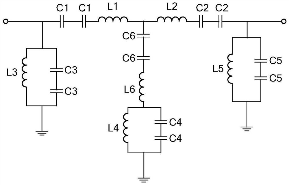
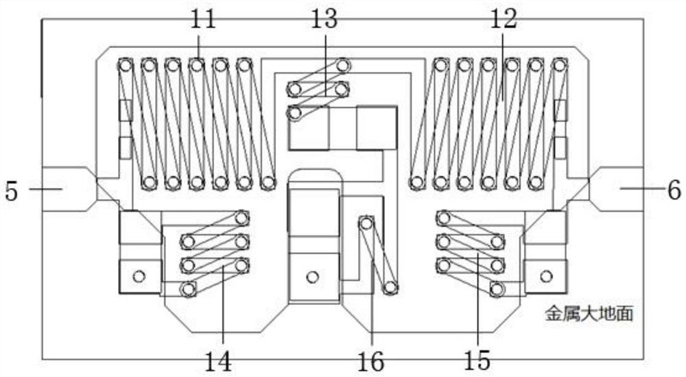
[0024] Such as figure 1 As shown in the circuit schematic diagram of the present invention, the filter circuit structure includes three LC series resonators and three LC parallel resonators. Wherein, the first LC series resonator 11 is a series resonator of an inductor L1 and two capacitors C1; the second LC series resonator 12 is a series resonator of an inductor L2 and two capacitors C2; the third LC series resonator 13 is an inductor L6 and two capacitors C6 series resonator. The first LC parallel resonator 14 is a parallel resonator of an inductor L3 and two capacitors C3; the second LC parallel resonator 15 is a parallel resonator of an inductor L4 and two capacitors C4; the third LC parallel resonator 16 is an inductor L5 and two capacitors. A capacitor C5 parallels the resonator. The connection mode of the circuit is: the input terminal 5 is connected to the first LC series resonator 11 (inductance L1, capacitor C1), the first LC series resonator 11 is connected to th...


PUM


Abstract

The invention relates to the technical field of band-pass filters, in particular to a high-performance miniaturized IPD band-pass filter. The IPD band-pass filter comprises an input end, an output end, a large-area metal ground, a capacitor dielectric layer, a substrate and a band-pass filter circuit, wherein the band-pass filter circuit is composed of three LC parallel resonators and three LC series resonators, the inductors are zigzag inductors, inductance coils are distributed on the upper surface of the substrate and are connected through through holes to form zigzag vertical spiral zigzag inductors, and the capacitors are MIM capacitors. The filter has the advantages of low insertion loss, high suppression, small size, high stability, suitability for batch processing, multiple harmonic suppression and the like.

Description

technical field [0001] The invention relates to the technical field of band-pass filters, in particular to a high-performance miniaturized IPD band-pass filter. Background technique [0002] A bandpass filter is a device that allows certain frequency bands to pass while blocking other frequency bands. An ideal filter should have a completely flat passband, i.e. no gain or attenuation within the passband, and all frequencies outside the passband are completely attenuated, and transitions outside the passband occur at extremely small frequencies Range complete. In fact, there is no ideal band-pass filter, especially with the development of electronic whole system in the direction of miniaturization and light weight. [0003] Traditional bandpass filters occupy too much chip area and cannot meet the miniaturization requirements of RF front-end devices. In order to meet the miniaturization needs of communication equipment devices, the initial search for high dielectric constan...

Claims


Application Information

Patent Timeline
Patent Type & Authority Applications(China)
IPC IPC(8): H03H7/01H01F27/30
CPCH03H7/0161H01F27/306
Inventor 刑孟江代传相
Owner YANGTZE DELTA REGION INST OF UNIV OF ELECTRONICS SCI & TECH OF CHINE HUZHOU
Why Eureka
Try Eureka